Automatic dimensions
A solid read from a STEP file or built in OpenCASCADE carries no sketch, so its views have no dimensions to draw. dw.AutoDimension() finds them from the view itself, as a drafter would. The view’s visible edges become a sketch of their own, with the id "Auto", and planex2d’s auto constraints find in it what a drafter would see, such as tangent edges, concentric circles, symmetry about an axis, equal holes on a bolt circle or in rows, and the datum
the sizes are measured from. The dimensions then follow a drafter’s order. Angles come before diameters and radii, and those before distances, with the horizontal and vertical distances first. Round values come before all others.
Dimensioning a part without its sketches is hard. A STEP file holds the part’s faces and edges but not the design intent behind them, so the dimensions are a reading of that intent from the geometry. Where a symmetry or a pattern is found that the designer did not mean, or a size is measured from a different edge than the designer’s, the drawing differs from the one the designer would make. Check every drawing before it is used.
The generated dimensions follow these rules:
Equal holes, and groups of edges repeated about a center or in rows, become one instance and a pattern of it, dimensioned once with their count. The count includes circles and arcs that are mirror images about an axis the part is symmetric about. The holes of a bolt circle get its pitch circle as a center line.
An axis the part is symmetric about is drawn as a center line.
Positions are measured from the part’s datum, never from an axis of the view’s plane that no point of the part lies on. This applies to sections as well, whose plane’s axes often run through the middle of the part.
On a
px.Sheet, each size is drawn once, in the first view that shows it. A view where a circular pattern is seen round comes first, then the front view, the top view, the side views, sections and other views. A diameter goes to the view where its circle appears round.A turned part, such as a shaft, a disc or a flange, gets its diameters in the view along its axis, written ⌀25, and its axis as a center line. The view where those circles are round does not repeat them.
The outline of a curved face seen side-on gets dimensions where the face is a convex face of revolution, such as a shaft’s outline or a fillet, or is round about a center line the view draws. Other outlines, such as a flute or a blade, are drawn without dimensions, and their sizes come from the view where they are seen round.
The dimensions of the view’s own sketches, added with
dw.Add(sk), come first, and the generated ones complete them.Chamfers are found on the solid. Their lines are drawn without dimensions, the sizes go to the sharp corners, and each chamfer gets one callout, its leg times 45°.
PlaceandHidemove and hide the generated dimensions as they do a sketch’s.
AutoDimension() works on a view of a solid along a plane, sections included. It raises an error on a pictorial and on the drawing of a sketch, which already shows the sketch’s own dimensions.
[1]:
import netgen.occ as occ
import planex as px
A part from a STEP file
The example is the bearing plate with its hub from Views of solids, 120 × 80 and 10 thick, with a bore of 40, four holes of 9 on a bolt circle of 60 and a hub of 48, 15 high. It is written to a STEP file and read back, the way a part from another CAD program arrives. netgen reads the file through OpenCASCADE, in millimeters, and the solid that comes back has its faces and edges but no sketch:
[3]:
part = px.Pad(plate, 10)
top = part.faces.Max(occ.Z)
part = part + px.Pad(px.QuickSketch(top).Circle((0, 0), 24).Circle((0, 0), 20), 15)
part.WriteStep("bearing_plate.step")
solid = occ.OCCGeometry("bearing_plate.step").shape
print("volume", solid.mass, "written", part.mass)
volume 88633.36324000737 written 88633.36324000738
The file is bearing_plate.step.
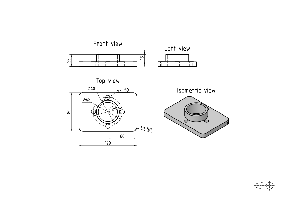
AutoDimension() dimensions each of the three views, and the sheet places them in first-angle projection, with the isometric view in the free corner between the left view and the top view. Each size is drawn once on the sheet. The top view comes first, since the bolt circle is seen round there. It gives the plate’s length and width, the circles, the four corner radii and the bore’s position, the front view adds the two heights, and the left view adds nothing:
[4]:
views = [px.Drawing(solid, plane, unit=px.mm).AutoDimension() for plane in (px.Front, px.Top, px.Left)]
px.Sheet(*views, px.Drawing(solid, px.Isometric, unit=px.mm), landscape=True)
[4]:
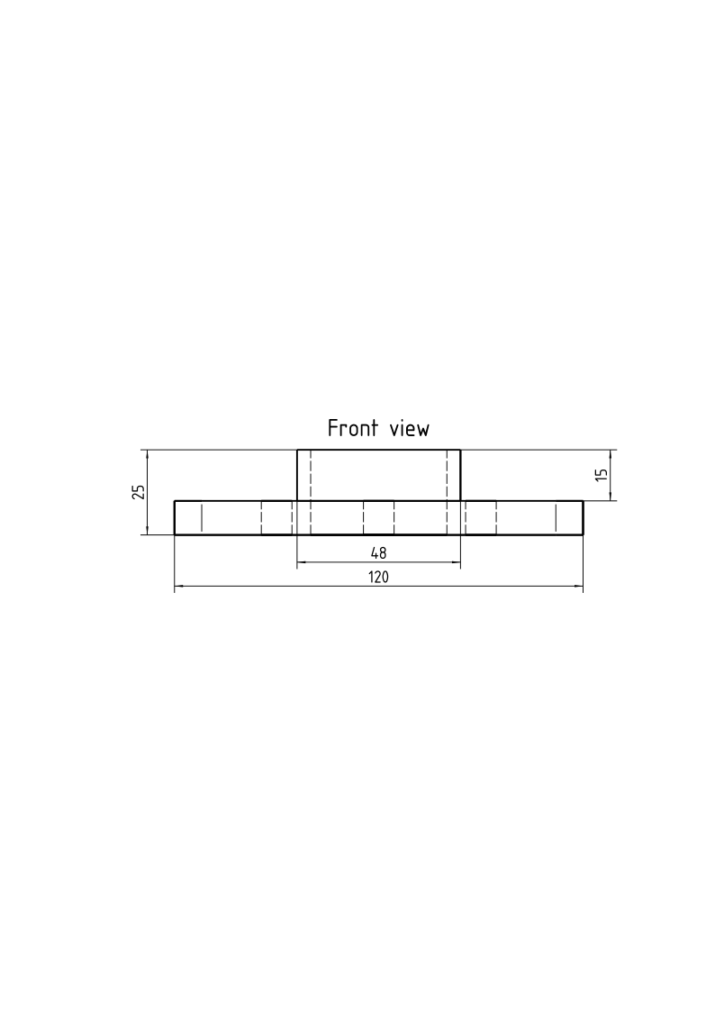
Drawn on its own, the front view keeps all of its dimensions, the plate’s length among them. The hub’s diameter, which the sheet gives in the top view where the hub appears round, is a length of 48 here:
[5]:
views[0]
[5]:
The part’s own sketches first
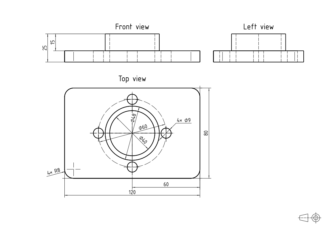
Where a sketch of the part is at hand, its dimensions are the designer’s and come first. Add puts the plate’s sketch on the top view, as on Views of solids, and AutoDimension() adds what the sketch leaves open, the hub’s diameter in the top view and the hub’s height and the overall height in the front view. On Views of solids, these two heights were added by hand with Measure. AutoDimension() also measures the bore’s axis 60 from the
plate’s right edge, although the sketch already fixes it by centering the plate on the origin. The next section hides such a dimension.
[6]:
front = px.Drawing(part, px.Front, unit=px.mm).AutoDimension()
top_view = px.Drawing(part, px.Top, unit=px.mm).Add(plate).AutoDimension()
left = px.Drawing(part, px.Left, unit=px.mm).AutoDimension()
px.Sheet(front, top_view, left, landscape=True)
[6]:
Moving and hiding dimensions
The generated dimensions have ids like a sketch’s, such as Distance.1 and Diameter.2, numbered in the order they are generated. An id that the view does not have raises an error that lists the ones it has:
[7]:
try:
    views[1].Hide("pitch")
except ValueError as err:
    print(err)
Drawing.Hide: 'pitch' is no dimension of the drawing's sketches; they have Diameter.1, Diameter.2, Diameter.3, Diameter.4, Distance.1, Distance.2, Distance.3, Radius.1
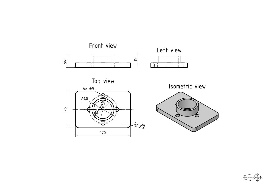
The top view from the STEP file measures the bore’s axis 60 from the plate’s right edge. The plate is symmetric about that axis, as its center lines show, so the 60 adds nothing to the length of 120. Hide leaves it out, and Place puts the bolt circle’s diameter on the other diagonal:
[8]:
views[1].Hide("Distance.3").Place("Diameter.1", "sw")
px.Sheet(*views, px.Drawing(solid, px.Isometric, unit=px.mm), landscape=True)
[8]:
Chamfers
A chamfer cuts off an edge with a narrow face. A drafter draws its lines without dimensions, gives the sizes to the sharp corner where the two faces it cuts would meet, and writes the chamfer as one callout, its leg times 45°. AutoDimension() finds chamfers on the solid itself, as chains of narrow faces between two faces, with the same legs all along. A chamfer is at most a tenth of the narrower face it cuts or 2 mm, whichever is larger, so a larger 45° bevel counts as part of the design and
is dimensioned as geometry.
The example is a block of 60 × 40 × 20 whose four vertical edges are chamfered by 2 with netgen.occ’s MakeChamfer. In the front view, the length of 60 runs to the sharp corners, and each of the two chamfers in front gets a callout:
[9]:
block = occ.Box(occ.Pnt(0, 0, 0), occ.Pnt(60, 40, 20))
block = block.MakeChamfer(block.edges[occ.Z > 1][occ.Z < 19], 2)
px.Drawing(block, px.Front, unit=px.mm).AutoDimension()
[9]:
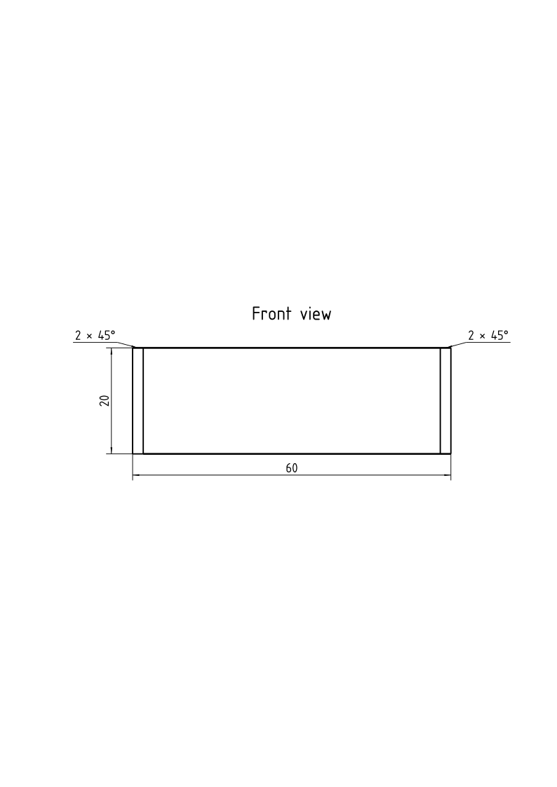
On a sheet, each chamfer gets one callout, in a view where it is seen end-on if there is one. A size that three or more chamfers of the sheet share goes into a general note at the bottom of the sheet instead, above the title block when there is one, here “Unspecified chamfers 2 × 45°” for all four:
[10]:
views = [px.Drawing(block, plane, unit=px.mm).AutoDimension() for plane in (px.Front, px.Top, px.Left)]
px.Sheet(*views, px.Drawing(block, px.Isometric, unit=px.mm), landscape=True)
[10]:
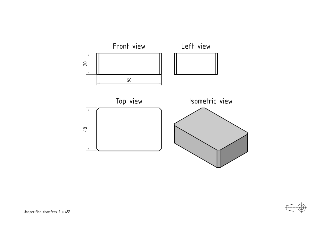
Place turns the callout’s leader by an angle or a compass direction, as for a radius, and Hide leaves it out. A leg with decimals is written with a decimal comma, such as “0,4 × 45°”, and with standard="ASME" with a decimal point, “0.4 × 45°”.
See Views of solids for the views themselves, Sections for cuts, and Placing dimensions for what Place takes.