Adjusting plate
An adjusting plate turns about a pivot and is clamped at the angle it is set to, by a screw through its arc slot. Its outline is a fan around the pivot, with a boss around the pivot’s back, and the slot is an arc about the same center, placed by its radius and two angles. Model the plate from the drawing in planex2d or in any CAD system, then check its area against the value at the end of the page. A solution in planex2d follows.

[1]:
import math
import planex as px
The outline
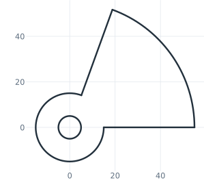
The outline is one chain from the boss out, the lower edge along x, the rim around the pivot, the upper edge back in and the boss around the pivot’s back. Turn turns the pen at a corner, and each arc starts along the pen’s direction. With auto_constraint={"horizontal": True}, the lower edge, drawn level, stays level, and the rim and the boss, drawn around one center, stay concentric. The chain ends where it started, and the sketch ties its two ends itself. The pivot hole goes into the
boss’s center with concentric=, which the auto constraints keep as well (Figure 1).
[3]:
plate = px.Sketch(auto_constraint={"horizontal": True})
plate.Move((15, 0), dir=(1, 0)).Line(40, id="lower_edge")
plate.Turn(90).Arc(55, 70, id="rim")  # Turn(90) turns the pen left: the rim starts at a corner
plate.Turn(90).Line(40, id="upper_edge")
plate.Turn(-90).Arc(15, 290, id="boss")
plate.Circle(10 / 2, concentric="boss", id="pivot");
The slot
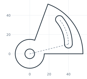
ArcSlot draws a slot along an arc from the pen, here of radius 40, turning 40° to the left, 8 wide. It is placed roughly, the pen at radius 40 and pointing up. The slot’s spine, the arc through the centers of its ends, is what its radius and angles are given on. A construction line from the pivot to the spine’s start carries its angle from the lower edge (Figure 2).
[5]:
plate.Move((40, 10), dir=(0, 1)).ArcSlot(40, 40, 8, id="slot")  # radius 40, 40° to the left, 8 wide
plate.Line("origin", "slot.spine.start", construction=True, id="slot_ray");
The dimensions
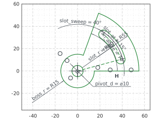
The pivot is the origin, and the lower edge starts on the horizontal axis. The slot’s spine shares the boss’s center with the rim, and the upper edge runs through it. The fan’s angle of 70° is the rim’s sweep, set with px.Angle on the arc. The slot’s spine sweeps 40°, and its start lies 15° above the lower edge. With the radii and the pivot’s diameter, nothing in the sketch is left free (Figure 3):
[7]:
plate.Constrain("boss.center", "origin", px.Coincident)
plate.Constrain("lower_edge.start", "H", px.Coincident)
plate.Constrain("origin", "upper_edge", px.Coincident)  # the point on the line's carrier: the edge is radial
plate.Constrain("boss", px.Radius, 15, id="boss_r")
plate.Constrain("rim", px.Radius, 55, id="rim_r")
plate.Constrain("rim", px.Angle, 70, id="fan_angle")  # an arc's sweep
plate.Constrain("pivot", px.Diameter, 10, id="pivot_d")
plate.Constrain("slot.spine", "boss", px.Concentric)
plate.Constrain("slot.spine", px.Radius, 40, id="slot_r")
plate.Constrain("slot.spine", px.Angle, 40, id="slot_sweep")
plate.Constrain("lower_edge", "slot_ray", px.Angle, 15, id="slot_at")
print("status", plate.status, "| degrees of freedom", plate.dof)
status full | degrees of freedom 0
The checks
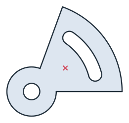
These are the area and the centroid, with the pivot at the origin, to compare with your own model. The area is the fan, 70/360 of a disc of radius 55, and the boss, 290/360 of a disc of radius 15, less the pivot hole and the slot. The slot is 40/360 of the ring between the radii 36 and 44, with its two half-disc ends of radius 4 (Figure 4):
[9]:
face = plate.Face()
exact = (70 / 360 * math.pi * 55**2 + 290 / 360 * math.pi * 15**2 - math.pi * 5**2
         - (40 / 360 * math.pi * (44**2 - 36**2) + math.pi * 4**2))
c = face.center
print("area", round(face.mass, 2), "mm², exact", round(exact, 2))
print("centroid", tuple(round(v, 2) for v in c[:2]))
area 2065.07 mm², exact 2065.07
centroid (20.5, 14.36)
The plate as DXF in millimeters, for another CAD system or a laser cutter:
[11]:
plate.WriteDXF("adjusting_plate.dxf", unit=px.mm, scale=1) # scale=1: the numbers as they are
The plate as DXF: adjusting_plate.dxf