Simulation-ready geometry
A finite-element model needs more than an outline. Its regions must share their interfaces, every boundary that gets a condition needs a name, periodic sides must be identified point by point, and the mesh must be fine where the solution changes fast. planex2d sets all of this on the geometry and passes it to netgen in one call, so that the mesh carries the materials, the boundary names and the identified pairs that NGSolve uses. The faces can come from a planar BREP or STEP file, a DXF or SVG drawing, a sketch from a .CATPart file, a circuit board or a Shapely polygon. The first cell is the complete workflow, ready to copy and run, and the section Step by step runs it in parts, with the plots one looks at along the way.
The example is one cell of a finned heat sink, as wide as the fin pitch of 10 mm. An aluminum base 4 mm thick carries a fin 2 mm thick and 20 mm high, and a copper spreader of 6 × 1 mm under the fin takes the heat of the component. The two faces come without names in the planar BREP file heat-sink-cell.brep, as geometry from another tool often does.
[2]:
import ngsolve as ngs
from ngsolve_webgpu.jupyter import Draw
import planex as px

aluminum, copper = sorted(px.FromBrep("heat-sink-cell.brep"), key=lambda f: -f.mass)
aluminum.name, copper.name = "aluminum", "copper"
cell = px.Glue([aluminum, copper])

cell.edges.name = "air"
cell.edges[px.y <= 0].name = "insulated"
cell.faces(name="copper")[0].edges.Max(px.y).name = "interface"
cell.edges.Min(px.y).name = "source"
cell.edges.Min(px.x).name = "left"
cell.edges.Max(px.x).name = "right"
cell.Identify("left", "right")
cell.edges(name="source").maxh = 0.0002

mesh = ngs.Mesh(px.OCCGeometry(cell).GenerateMesh(maxh=0.0005))
print(mesh.ne, "elements |", mesh.GetMaterials(), "|", sorted(set(mesh.GetBoundaries())))
print(len(mesh.ngmesh.GetIdentifications()), "identified point pairs")
plain, periodic = ngs.H1(mesh, order=2), ngs.Periodic(ngs.H1(mesh, order=2))
print("free degrees of freedom", sum(plain.FreeDofs()), "plain |", sum(periodic.FreeDofs()), "periodic")
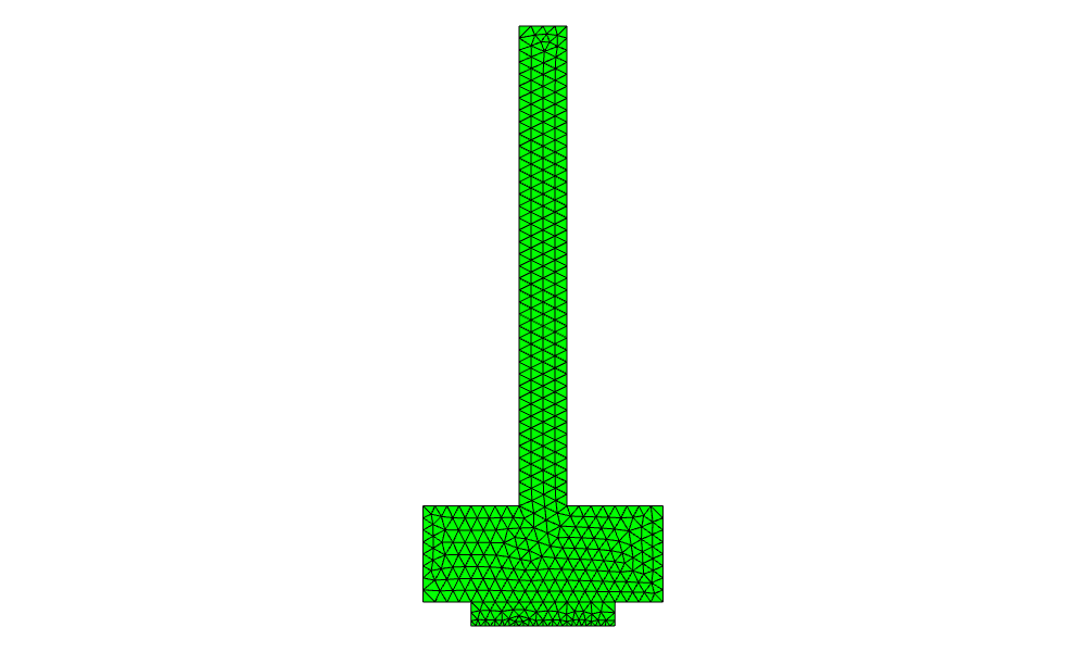
Draw(mesh)
782 elements | ('aluminum', 'copper') | ['air', 'insulated', 'interface', 'left', 'right', 'source']
9 identified point pairs
free degrees of freedom 1725 plain | 1708 periodic
Step by step
Reading and gluing
px.FromBrep reads the two planar faces as a compound, in meters, and sorting by area tells the aluminum from the copper. Their names become the materials of the mesh. px.Glue cuts the two faces against each other into one shape, so that the top of the copper and the part of the base above it become one edge that both faces share, and the mesh then has matching nodes on both sides of the interface (see Faces, shapes and compounds and STEP
and BREP).
[3]:
import ngsolve as ngs
from ngsolve_webgpu.jupyter import Draw
import planex as px

aluminum, copper = sorted(px.FromBrep("heat-sink-cell.brep"), key=lambda f: -f.mass)
aluminum.name, copper.name = "aluminum", "copper"
cell = px.Glue([aluminum, copper])
print(len(cell.faces), "faces,", len(cell.edges), "edges")
2 faces, 13 edges
Naming the boundaries
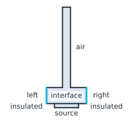
cell.edges.name names every edge at once, here air for the convection to the surrounding air. Selections then rename the others by where they lie, with no coordinate taken from the drawing. The origin is the bottom left corner of the base, so edges[px.y <= 0] takes the edges whose middle lies at or below the base’s bottom, the bottom of the base beside the copper and the copper’s edges, as insulated. The highest of the copper face’s edges, Max(px.y), is the interface that
both faces share. Of all edges, the lowest is the bottom of the copper, the heat source, and the leftmost and rightmost are the two sides of the cell, left and right (Figure 1). See Picking what to measure for these selections and Naming and marking for the names in the mesh.
[4]:
cell.edges.name = "air"
cell.edges[px.y <= 0].name = "insulated"
cell.faces(name="copper")[0].edges.Max(px.y).name = "interface"
cell.edges.Min(px.y).name = "source"
cell.edges.Min(px.x).name = "left"
cell.edges.Max(px.x).name = "right"
print(sorted({e.name for e in cell.edges}))
# px.Plot(cell)
['air', 'insulated', 'interface', 'left', 'right', 'source']
Periodic sides and mesh sizes
The heat sink repeats every 10 mm, so the cell’s left and right sides carry the same temperature. Identify pairs the two sides, and planex2d finds the shift between them, so netgen places the nodes of both sides in pairs (see Identifications). A maxh on an edge refines the mesh there, here 0.2 mm at the heat source, against 0.5 mm elsewhere (see Meshing a face).
[6]:
cell.Identify("left", "right")
cell.edges(name="source").maxh = 0.0002
Meshing and checking
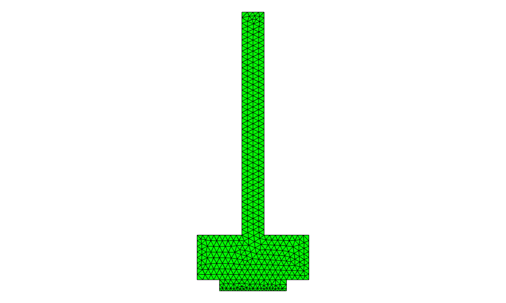
netgen meshes the shape with both materials and all the names, and the identification gives node pairs, each shifted by exactly one fin pitch. NGSolve’s Periodic space uses the pairs and has fewer free degrees of freedom than the plain one, since each pair carries one value. gmsh takes the same shape through WriteGeo, with the edge names as physical groups (see gmsh and FEniCSx).
[7]:
mesh = ngs.Mesh(px.OCCGeometry(cell).GenerateMesh(maxh=0.0005))
print(mesh.ne, "elements |", mesh.GetMaterials(), "|", sorted(set(mesh.GetBoundaries())))
print(len(mesh.ngmesh.GetIdentifications()), "identified point pairs")
plain, periodic = ngs.H1(mesh, order=2), ngs.Periodic(ngs.H1(mesh, order=2))
print("free degrees of freedom", sum(plain.FreeDofs()), "plain |", sum(periodic.FreeDofs()), "periodic")
Draw(mesh)
782 elements | ('aluminum', 'copper') | ['air', 'insulated', 'interface', 'left', 'right', 'source']
9 identified point pairs
free degrees of freedom 1725 plain | 1708 periodic
Other formats
Format |
Reader |
Names it brings |
See |
|---|---|---|---|
BREP (planar) |
|
None |
|
STEP (planar) |
|
Names, colors, mesh sizes |
|
DXF |
|
Layers as edge names |
|
SVG |
|
Groups as edge names |
|
KiCad, Altium, Eagle and other boards |
|
Nets as face names |
|
.CATPart sketches |
|
Element names as ids |
Pitfalls
Unglued regions. Faces that only touch, without
px.Glue, are meshed separately, with nodes that do not match at the interface.Names after gluing. Gluing cuts edges, so boundaries are named on the glued shape, not on the faces before.
Units. The geometry is in meters, so every
maxhis in meters too.Matching sides. Identified sides must be congruent, here two straight sides of equal length. A side cut into pieces on one end and not on the other cannot be paired.