Flange drawings from a design table
A part made in several sizes can be documented on one tabulated drawing, with its dimensions as letters and a table of their values, as in the exercise Flange series. A drawing per size is the other way. Each size gets its own sheet and drawing number, with the values written out, so that the workshop reads them off without a table. When the sizes come from one parametric model, these drawings are not drawn one by one. Each one is the model, updated to a row of its design table, drawn again.
The example is the flange of that exercise in its three sizes, a disc with a bore and holes on a bolt circle midway between the bore and the outside. Lengths are in mm.
This page is part of a collection of manufacturing examples using planex2d.
Open this example in the playground, the interactive code editor in the browser, to change the code and run it.

[1]:
import planex as px
The model
The sketch is the exercise’s, with one change for the drawings. The bolt circle is a construction circle through the first hole’s center, and its diameter k is a dimension, which a drawing shows like any other. An expression ties it to the rule \(k = (D + d)/2\), so that it follows the outside and the bore in every size. CircularPattern repeats the hole, with the number of holes as the dimension holes.count. The dimensions have the letters of the design table as their ids (Figure
1):
[3]:
flange = px.Sketch(auto_constraint=True)
flange.Circle(50, id="outside")
flange.Circle(15, id="bore")
flange.Circle(32.5, construction=True, id="pitch")
flange.Circle(5.5, center=(32.5, 1), id="hole")
flange.Constrain("outside.center", "origin", px.Coincident)
flange.Constrain("hole.center", "pitch", px.Coincident)
flange.Constrain("hole.center", "H", px.Coincident)
flange.Constrain("outside", px.Diameter, 100, id="D")
flange.Constrain("bore", px.Diameter, 30, id="d")
flange.Constrain("pitch", px.Diameter, 65, id="k")
flange.Constrain("hole", px.Diameter, 11, id="l")
flange.Expression("k = (D + d) / 2", id="bolt_circle")
flange.CircularPattern(["hole"], "origin", 4, id="holes")
print("status", flange.status, "| degrees of freedom", flange.dof)
# flange.Plot(show_constraints=True)
status full | degrees of freedom 0
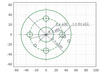
A drawing per size
The design table has a row of dimensions for each size, in the form that sk.ReadSpreadsheet returns from a spreadsheet. px.Drawing keeps the sketch by reference, so one drawing serves all sizes. For each row, Update solves the sketch, the drawing’s own Update draws it again, and px.Sheet puts it on an A4 sheet with a frame and planex2d’s default title block. The block fills in the scale, the paper size, the date and the sheet number itself, and the drawing number names the
size. The bolt circle’s diameter stands on a leader at 67.5°, which runs between the holes in every size. Each sheet is written as a PDF:
[5]:
sizes = {"A": {"D": 100, "d": 30, "l": 11, "holes.count": 4},
         "B": {"D": 125, "d": 45, "l": 13.5, "holes.count": 4},
         "C": {"D": 160, "d": 60, "l": 13.5, "holes.count": 8}}
drawing = px.Drawing(flange, unit=px.mm).Place("k", 67.5, leader=True)
for name, size in sizes.items():
    flange.Update(size)
    drawing.Update()
    sheet = px.Sheet(drawing, frame=True)
    sheet.Title(title="Flange", subtitle=f"Size {name}", number=f"FL-{size['D']}")
    sheet.WritePDF(f"flange_{name}.pdf")
    print(name, "k", flange["k"], "| (D + d) / 2", (size["D"] + size["d"]) / 2, "| holes", flange["holes.count"])
A k 65.0 | (D + d) / 2 65.0 | holes 4
B k 85.0 | (D + d) / 2 85.0 | holes 4
C k 110.0 | (D + d) / 2 110.0 | holes 8
The sheet of the last size, C, as it is written to its PDF:
[6]:
sheet
[6]:
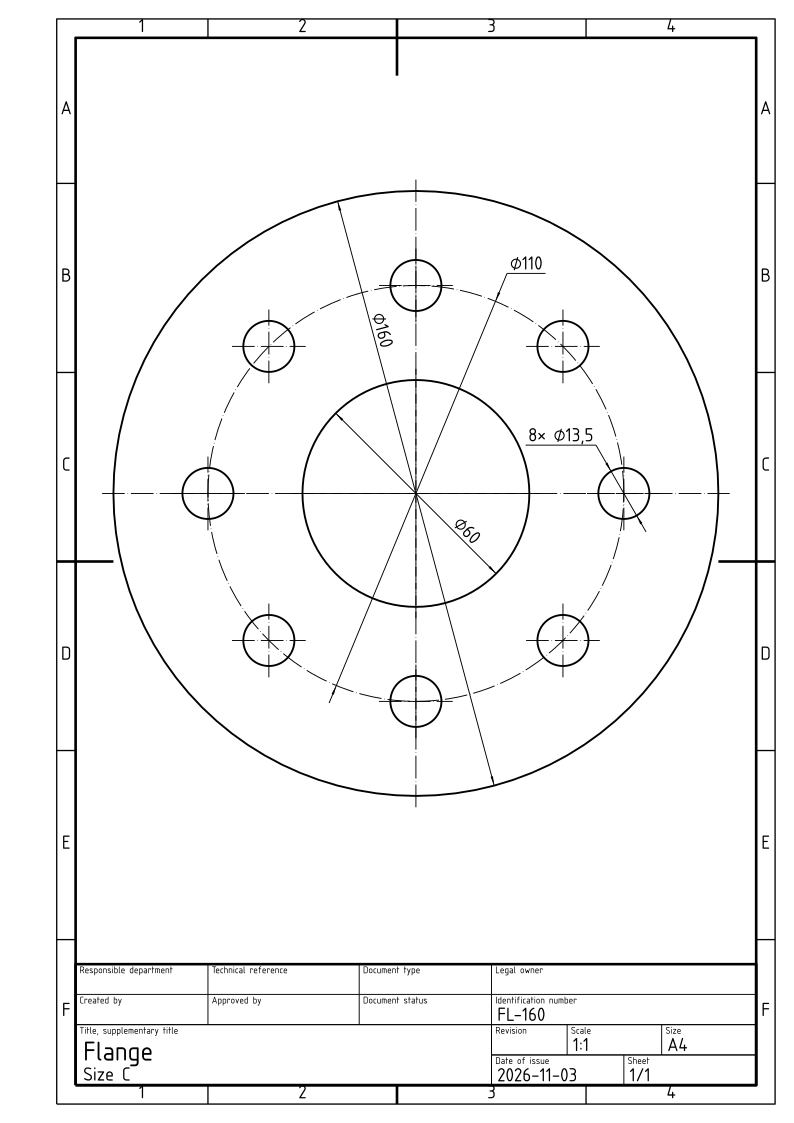
The drawings as PDF: flange_A.pdf, flange_B.pdf, flange_C.pdf
See Views and sheets and Title blocks and files for sheets and title blocks, and Design tables in a spreadsheet for rows read from a file.