Gear pump cover
The cover closes the housing of the gear pump over its gasket. It carries the bearings of the two gear shafts, the rotors, and lets the drive shaft out through a seal. Its outline and its bolt holes are the gasket’s, so they come from the same opening and the same bolt line, and the bearings are bores into bosses around the gears’ centers. Model the cover from the drawing in planex2d or in any CAD system, then check its volume, mass and center of mass against the values at the end of the page. A solution in planex2d follows.

[1]:
import math
import netgen.occ as occ
import planex as px
The plate
The cover’s outline is the gasket’s, the two chambers of 38.5 around the gears’ centers, 34 apart on the \(x\) axis, united and offset 16 outward. The bolt line is the opening offset by 8. The plate is the outline padded 12 up from the xy plane, which is the face against the gasket (Figure 1):
[3]:
opening = px.Unify([px.Circle((-17, 0), 38.5 / 2).Face(), px.Circle((17, 0), 38.5 / 2).Face()]).Face()
outline = opening.Offset(16, inplace=False).Face()  # as the gasket's
bolt_line = opening.Offset(8, inplace=False).Face().outer
plate = px.Pad(outline, 12)
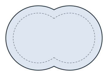
(a) The outline, the bolt line dashed
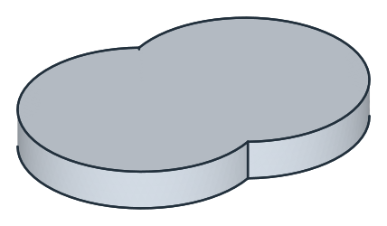
(b) Padded 12
The boss and the bores
A boss stands 8 above the plate around both gears’ centers. It is two discs of 36 around them, united into one figure eight, so that no narrow gap stays between them, sketched on the plate’s top and padded. The idler gear’s shaft, on the left, runs in a blind bore of 15, 10 deep from the underside. The drive shaft, on the right, passes through a bore of 15 through the plate and its boss, and a seal sits in a seat of 24, 5 deep, at the boss’s top (Figure 2):
[5]:
boss = px.Unify([px.Circle((-17, 0), 18).Face(), px.Circle((17, 0), 18).Face()]).Face()
cover = plate + px.Pad(boss.Translated((0, 0, 12)), 8)
idler = px.QuickSketch(px.XY).Circle(15 / 2, center=(-17, 0))  # on the underside's plane
cover = px.Pocket(cover, idler, 10, reverse=True)  # 10 deep, along the plane's normal: up into the plate
drive = px.QuickSketch(px.Plane(px.XY, 20)).Circle(15 / 2, center=(17, 0))  # the boss's top, 12 + 8 up
cover = px.Pocket(cover, drive, 20)
seal = px.QuickSketch(px.Plane(px.XY, 20)).Circle(24 / 2, center=(17, 0))
cover = px.Pocket(cover, seal, 5)
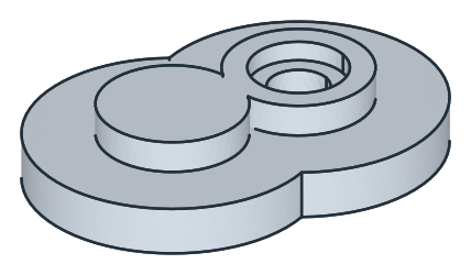
The bolt holes
The ten holes lie where the gasket’s do, equally spaced along the bolt line, the first half a pitch from the corner where it starts. along walks the bolt line with PointAt, as on the gasket’s page. Each hole is a clearance hole of 6.6 through the plate with a counterbore of 11, 6.5 deep from the top, for an M6 socket head screw (Figure 3):
[7]:
def along(wire, n):
    """n points equally spaced along a closed wire, the first half a pitch from its start"""
    pitch = wire.mass / n
    targets = [pitch / 2 + k * pitch for k in range(n)]
    points, walked = [], 0.0
    for e in wire.edges:
        length = e.Measure()["length"]
        points += [e.PointAt((t - walked) / length) for t in targets if walked <= t < walked + length]
        walked += length
    return [(p.x, p.y) for p in points]


centers = along(bolt_line, 10)
counterbores = px.QuickSketch(px.Plane(px.XY, 12))
holes = px.QuickSketch(px.Plane(px.XY, 12))
for c in centers:
    counterbores.Circle(11 / 2, center=c)
    holes.Circle(6.6 / 2, center=c)
cover = px.Pocket(cover, counterbores, 6.5)
cover = px.Pocket(cover, holes, 12)
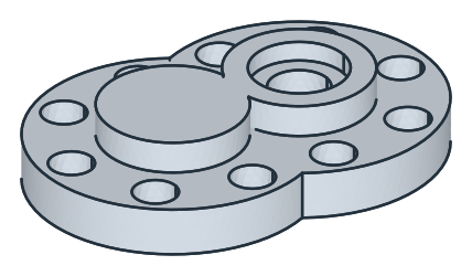
The checks
These are the volume, the mass in aluminum EN AC-AlSi10Mg (2.68 g/cm³) and the center of mass, with the origin in the middle between the gears’ centers on the underside, to compare with your own model. The outline is the union of two circles of 35.25 and the boss the union of two of 18, each \(2 \pi r^2\) less the lens of the two circles, \(2 r^2 \arccos\left(\tfrac{d}{2r}\right) - \tfrac{d}{2} \sqrt{4 r^2 - d^2}\). Every other part is a cylinder or a ring. The cover is symmetric about the plane \(y = 0\), so its center of mass lies in it:
[9]:
def union(r, d=34):
    return 2 * math.pi * r**2 - (2 * r**2 * math.acos(d / (2 * r)) - d / 2 * math.sqrt(4 * r**2 - d**2))


def disc(d):
    return math.pi * d**2 / 4


exact = (union(35.25) * 12 + union(18) * 8 - disc(15) * 10 - disc(15) * 20 - (disc(24) - disc(15)) * 5
         - 10 * disc(6.6) * 12 - 10 * (disc(11) - disc(6.6)) * 6.5)
c = cover.center
print("volume", round(cover.mass, 2), "mm³, exact", round(exact, 2))
print("mass", round(cover.mass * 2.68e-6, 4), "kg")
print("center of mass", (round(c.x, 4), round(c.z, 4)), "| off the plane y = 0 by", round(abs(c.y), 6))
volume 75870.41 mm³, exact 75870.41
mass 0.2033 kg
center of mass (-0.7048, 7.6146) | off the plane y = 0 by 0.0
The cover as STEP, for another CAD system:
[10]:
cover.WriteStep("pump_cover.step")
The cover as STEP: pump_cover.step