Preparing parts for laser cutting
A part to be cut by a laser, a waterjet or a plasma cutter needs a few checks and one change before it goes to the machine. Its webs and openings must not be narrower than the sheet is thick, the cutting path runs half the kerf outside the part, and cut length and pierces give the cutting time. planex2d does all of it on the exact geometry and writes the path as DXF. The part can come from a planar STEP or BREP file, a DXF or SVG drawing, a sketch from a .CATPart file or a Shapely polygon. The first cell is the complete workflow, ready to copy and run, and the section Step by step runs it in parts, with the plots one looks at along the way.
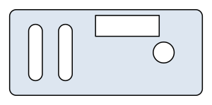
The example is a sensor bracket cut from steel sheet 2 mm thick, 90 × 40 mm with corners of radius 3, two adjustment slots 6.6 wide, a hole of diameter 10 and a window of 30 × 10 near its top edge. The file sensor-bracket.step was exported from a 3D CAD program as a planar STEP file in millimeters.
[2]:
import planex as px
import planex.measurements as pm

bracket = px.FromStep("sensor-bracket.step")
print("thinnest web", bracket.Measure(pm.MinThickness()), "| sheet", 0.002)
print("smallest opening", min(min(w.bounding_box[1][i] - w.bounding_box[0][i] for i in (0, 1)) for w in bracket.inner))

cut = bracket.Offset(0.0001, inplace=False)
print("cut length", sum(w.mass for w in cut.wires), "| pierces", len(cut.wires))
px.WriteDXF(cut.wires, "sensor-bracket-cut.dxf", unit=px.mm)
cut
thinnest web 0.002499999999998865 | sheet 0.002
smallest opening 0.006600000000000002
cut length 0.48567786842338584 | pierces 5
[2]:
Step by step
Reading the part
px.FromStep reads the planar face of the STEP file, with its holes, and converts the file’s millimeters into meters, as every reader of planex2d does (see STEP and BREP and Units). The bracket is one face with four openings.
[3]:
import planex as px
import planex.measurements as pm

bracket = px.FromStep("sensor-bracket.step")
print(type(bracket).__name__, "with", len(bracket.inner), "openings | size", bracket.bounding_box)
# px.Plot(bracket)
Face with 4 openings | size ((-2.6020852139652106e-18, 0.0), (0.09000000000000002, 0.04))
Checking webs and openings
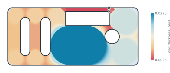
A common rule for laser-cut steel is that no web and no opening is narrower than the sheet is thick, here 2 mm. pm.MinThickness() rolls the largest disc that fits along the whole outline and returns the thinnest wall, 2.5 mm above the window. The wall-thickness map shows where it is (Figure 1). The narrowest opening is the smaller side of each opening’s bounding box, which is the width of a slot and the diameter of a hole. The narrowest are the slots, 6.6 mm wide. See Part
analysis for wall thickness, clearances and the other measurements.
[4]:
print("thinnest web", bracket.Measure(pm.MinThickness()), "| sheet", 0.002)
print("smallest opening", min(min(w.bounding_box[1][i] - w.bounding_box[0][i] for i in (0, 1)) for w in bracket.inner))
thinnest web 0.002499999999998865 | sheet 0.002
smallest opening 0.006600000000000002
The cutting path
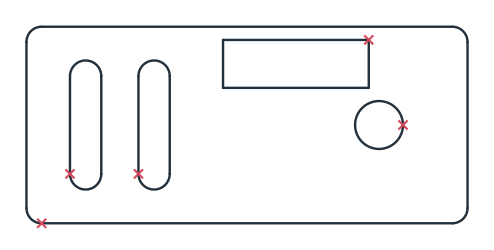
The laser cuts a slot as wide as its kerf, 0.2 mm here, so its path runs 0.1 mm outside the part, outward around the outline and inward into every opening. Offset of the face by 0.1 mm does both at once, since a positive offset grows the material, and inplace=False keeps the part as it is (see Offsets). Cut length is the length of all loops of the path, and every loop starts with one pierce of the sheet, five in all (Figure 2).
[6]:
cut = bracket.Offset(0.0001, inplace=False)
print("cut length", sum(w.mass for w in cut.wires), "| pierces", len(cut.wires))
cut length 0.48567786842338584 | pierces 5
Writing the cutting file
px.WriteDXF of the path’s loops writes them alone, without a fill, and unit=px.mm writes millimeters, converted from the meters of the geometry. Read back, the path is 0.1 mm larger on every side than the part. The file is sensor-bracket-cut.dxf. See Files for the other writers.
[8]:
px.WriteDXF(cut.wires, "sensor-bracket-cut.dxf", unit=px.mm)
print(px.Compound(px.FromDXF("sensor-bracket-cut.dxf")).bounding_box)
((-0.00010000000000000937, -0.00010000000000000026), (0.09010000000000001, 0.04010000000000001))
Other formats
Format |
Reader |
See |
|---|---|---|
STEP, BREP (planar) |
|
|
DXF |
|
|
SVG |
|
|
.CATPart sketches |
|
|
Shapely |
|
Pitfalls
Compensating twice. Many cutting controllers compensate the kerf themselves. For those, the part’s own outline goes into the file, without the offset.
Units. The geometry is in meters, so a kerf of 0.2 mm is an offset of 0.0001. The writer converts to the unit given, and
scale=1would write the meters’ numbers unchanged.Open contours. A drawing with gaps gives no closed loops to cut. See Cleaning up imported drawings.
The rule of thumb. Web and opening at least the sheet thickness is a common guide for steel. The actual limits depend on the material, the machine and the cutting shop.
In the browser
The contour checker checks a DXF, SVG or STEP file for open contours, gaps, doubled lines and small edges and gives cut length and pierces, and the nesting tool places many parts on a sheet or a roll.