Involute spur gears under load
The example is a pair of involute spur gears with a module of m = 2, a pressure angle of alpha = 20° and no profile shift: a pinion with 20 teeth and a wheel with 31. The flanks are involutes of the base circle, computed point by point and drawn as splines. Below the base circle, the flanks run radially, without a root fillet. Lengths are in

[1]:
import math
import netgen.occ as occ
import ngsolve as ngs
from ngsolve.webgui import Draw
import planex as px
A gear
One tooth is a sketch from the center out along one flank, over the tip and back down the other, and the teeth are united with the root circle. gear(z) draws a gear with z teeth, from the pitch radius m z / 2, the base radius, the tip radius one module above it and the root radius 1.25 modules below it (Figure 1).
[3]:
m = 2.0
alpha = math.radians(20)


def inv(a):
    return math.tan(a) - a


def gear(z):
    r = m * z / 2
    rb, ra, rf = r * math.cos(alpha), r + m, r - 1.25 * m
    beta = math.pi / (2 * z) + inv(alpha)
    ta = math.sqrt((ra / rb) ** 2 - 1)
    flank = []
    for i in range(21):
        t = ta * i / 20
        rt, phi = rb * math.sqrt(1 + t * t), -(beta - inv(math.atan(t)))
        flank.append((rt * math.cos(phi), rt * math.sin(phi)))
    other = [(x, -y) for x, y in flank]
    tip = 2 * math.degrees(beta - inv(math.atan(ta)))
    tooth = px.QuickSketch().Line(flank[0]).Spline(flank[1:]).Arc(center=(0, 0), sweep=tip)
    tooth = tooth.Spline(other[::-1][1:]).Close().Face()
    teeth = [tooth.Rotated((0, 0), 360 * k / z) for k in range(z)]
    return px.Unify(teeth + [px.QuickSketch().Circle(rf).Face()])


z = 20
wheel = gear(z)
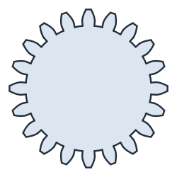
Check: the pitch circle, split by the gear, runs inside the teeth over a tooth thickness of π m / 2 each:
[5]:
pitch = px.QuickSketch().Circle(m * z / 2).Wire()
inside = []
for run in pitch.Split(wheel):
    p = run.wires[0].edges[0].midpoint
    if wheel.Contains((p.h, p.v), boundary=False):
        inside.append(run.wires[0].mass)
print(len(inside), "teeth, thickness", sum(inside) / z, "exact", math.pi * m / 2)
20 teeth, thickness 3.141592567868958 exact 3.141592653589793
A pair
The wheel with 31 teeth sits at the center distance m (z1 + z2) / 2, turned by half a pitch so that a tooth gap faces the pinion tooth on the line of centers (Figure 2). The two touch but do not overlap:
[6]:
z2 = 31
center = m * (z + z2) / 2
partner = gear(z2).Rotated((0, 0), 180 + 180 / z2).Translated((center, 0))
print("overlap", (wheel * partner).mass)
overlap 0.0

Teeth under load
The pinion is held at its bore of 12, and the wheel is turned by 0.002 rad at its bore of 16. Turned by another 0.2°, the wheel’s teeth overlap the pinion’s slightly where they touch. Gluing the two gears joins them over that overlap, so the load passes from tooth to tooth.
[8]:
pinion = wheel - px.QuickSketch().Circle(6, name="hold").Face()
driven = gear(z2).Rotated((0, 0), 180 + 180 / z2 + 0.2).Translated((center, 0))
driven = driven - px.QuickSketch().Circle(center, 0, 8, name="drive").Face()
pinion.name = "pinion"
driven.name = "wheel"
pair = px.Glue([pinion, driven])
mesh = ngs.Mesh(px.OCCGeometry(pair).GenerateMesh(maxh=0.5))
mesh.Curve(3)
[8]:
<ngsolve.comp.Mesh at 0x7fadbd205550>
NGSolve solves for plane stress in steel, with a Young’s modulus E of 210 000 N/mm² and a Poisson’s ratio nu of 0.3. The picture shows the von Mises stress on the deformation, magnified 20 times. Its colour scale ends at 30 % of the largest element mean of the stress.
[9]:
E = 210000.0
nu = 0.3
fes = ngs.VectorH1(mesh, order=2, dirichlet="hold|drive")
u, v = fes.TnT()

def strain(w):
    return ngs.Sym(ngs.Grad(w))

def stress(w):
    e = strain(w)
    return E / (1 - nu**2) * ((1 - nu) * e + nu * ngs.Trace(e) * ngs.Id(2))

a = ngs.BilinearForm(ngs.InnerProduct(stress(u), strain(v)) * ngs.dx).Assemble()
disp = ngs.GridFunction(fes)
disp.Set(ngs.CF((-0.002 * ngs.y, 0.002 * (ngs.x - center))), definedon=mesh.Boundaries("drive"))
disp.vec.data += a.mat.Inverse(fes.FreeDofs(), inverse="sparsecholesky") * (-a.mat * disp.vec)
s = stress(disp)
mises = ngs.sqrt(s[0, 0] ** 2 + s[1, 1] ** 2 - s[0, 0] * s[1, 1] + 3 * s[0, 1] ** 2)
peak = ngs.GridFunction(ngs.L2(mesh, order=0))
peak.Set(mises)
Draw(mises, mesh, deformation=20 * disp, min=0, max=0.3 * max(peak.vec))
The part
For the 3D part, a bore of 12 with a keyway 4 wide and 1.8 deep into the hub is added, and the gear is extruded to a width of 10.
[10]:
bore = px.QuickSketch().Circle(6).Face() + px.QuickSketch((-2, 0), dir=(1, 0)).Rectangle(4, 6 + 1.8).Face()
solid = (wheel - bore).ToOCCShape().Extrude(10)
solid.WriteStep("spur_gear.step")
Draw(solid)
The gear as STEP: spur_gear.step