Gear pump rotors
The rotors of the gear pump are two equal spur gears, each one piece with its shaft. The drive rotor’s shaft leaves the pump through the cover and is driven by a motor through a key, and the idler rotor is turned by the drive rotor. The gears turn in the housing’s chambers with little clearance at their tips, and the oil is carried round in the gaps between the teeth. Their flanks are involutes, a little thinner than nominal, so that the meshing teeth have backlash. Model both rotors from the drawing in planex2d or in any CAD system, then check the span over three teeth, the mesh, the clearance in the chambers and their volumes and masses against the values at the end of the page. A solution in planex2d follows.

[1]:
import math
import netgen.occ as occ
import planex as px
The gear
The gears have a module of \(m = 2\) and \(z = 17\) teeth, a pressure angle of \(\alpha = 20^\circ\) and no profile shift, so their pitch circles of 34 touch at the center distance of 34. Each flank is 0.025 thinner along the pitch circle than nominal, so each tooth is 0.05 thinner, and the pair has a backlash of 0.1 along the pitch circle, 0.05 at each flank when the teeth sit in the middle of their gaps. As on the spur gear, a flank is the involute of the base
circle, drawn from its formula with Curve from the base circle out to the tip circle. One tooth is a QuickSketch along a flank, over the tip and down the other flank, and the teeth are united with the root circle (Figure 1):
[3]:
m = 2
z = 17
alpha = math.radians(20)


def inv(a):
    return math.tan(a) - a


def gear(thinner=0.025):
    """the gear's face, its first tooth on the x axis, each flank thinner along the pitch circle by thinner"""
    r = m * z / 2
    rb = r * math.cos(alpha)  # the base circle
    ra = r + m  # the tip circle
    rf = r - 1.25 * m  # the root circle
    beta = math.pi / (2 * z) + inv(alpha) - thinner / r  # half the tooth's angle at the base circle
    ua = math.sqrt((ra / rb) ** 2 - 1)  # the roll angle at the tip circle
    b, tip = math.degrees(beta), 2 * math.degrees(beta - inv(math.atan(ua)))
    h = f"{rb}*(cos(t - {b}) + t*pi/180*sin(t - {b}))"
    v = f"{rb}*(sin(t - {b}) - t*pi/180*cos(t - {b}))"
    tooth = px.QuickSketch().Line((rb * math.cos(beta), -rb * math.sin(beta)))
    tooth.Curve((h, v), (0, math.degrees(ua))).Arc(center=(0, 0), sweep=tip)  # around the center
    tooth = tooth.Curve((h, f"-({v})"), (math.degrees(ua), 0)).Close().Face()
    teeth = [tooth.Rotated((0, 0), 360 * k / z) for k in range(z)]
    return px.Unify(teeth + [px.Circle((0, 0), rf).Face()]).Face()


face = gear()
print("tip", m * z + 2 * m, "| root", m * z - 2.5 * m, "| area", round(face.mass, 4), "mm²")
tip 38 | root 29.0 | area 877.0129 mm²
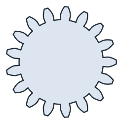
The mesh
In the pump, the gears’ centers lie at (−17, 0) and (17, 0). With an odd number of teeth, a gear whose first tooth points along \(+x\) has a gap pointing along \(-x\), so the two gears mesh unturned. Turned against each other, each by the same angle the other way, they keep meshing. The closest flanks stay apart by the gap at each flank along the line of action, \(2 \cdot 0.025 \cdot \cos\alpha\), at every position, a property of involute gears, and nothing overlaps (Figure 2):
[5]:
for turn in (0, 4, 8):
    left = face.Rotated((0, 0), turn).Translated((-17, 0))
    right = face.Rotated((0, 0), -turn).Translated((17, 0))
    overlap = left * right
    print("turned", turn, "° | overlap", round(overlap.mass, 9) if overlap.faces else 0.0,
          "| closest flanks", round(left.Distance(right), 5), "| 2 · 0.025 cos α", round(2 * 0.025 * math.cos(alpha), 5))
turned 0 ° | overlap 0.0 | closest flanks 0.04698 | 2 · 0.025 cos α 0.04698
turned 4 ° | overlap 0.0 | closest flanks 0.04698 | 2 · 0.025 cos α 0.04698
turned 8 ° | overlap 0.0 | closest flanks 0.04698 | 2 · 0.025 cos α 0.04698
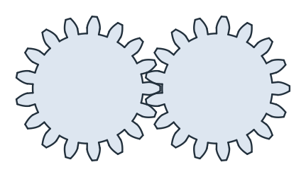
(a) The two gears meshing
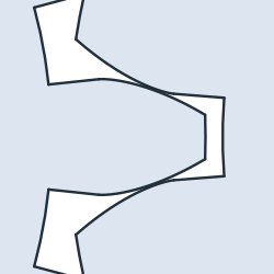
(b) Where they mesh
The rotors
Each gear is padded 20, the chambers’ depth, from the xy plane. The journals of 15 run in the housing’s bearing bores, 7 below the gear, and in the cover. The idler rotor’s journal reaches 9 above the gear, into the cover’s blind bore, and the drive rotor’s shaft 50 above it, through the cover and out of it. The journals are discs padded from the gear’s faces (Figure 3):
[7]:
def rotor(above):
    """a gear 20 wide with journals of 15, 7 below it and `above` above it"""
    body = px.Pad(face, 20)
    shaft = px.Circle((0, 0), 15 / 2).Face()
    body = body + px.Pad(shaft, 7, reverse=True)  # 7 down, below the gear
    return body + px.Pad(shaft.Translated((0, 0, 20)), above)


idler = rotor(9)
drive = rotor(50)
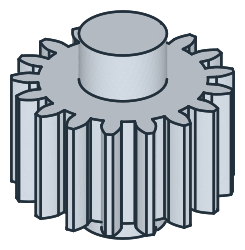
(a) The idler rotor
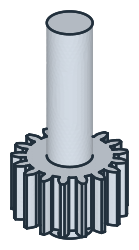
(b) The drive rotor
The drive shaft’s keyseat is 5 wide and 20 long with round ends, 3 deep, ending 5 below the shaft’s end at \(z = 70\). It is sketched on the plane tangent to the shaft at \(y = -7.5\), its \(h\) along \(z\), and pocketed into the shaft (Figure 4):
[9]:
tangent = px.Plane(origin=(0, -7.5, 0), normal=(0, -1, 0), axis=(0, 0, 1))  # h along the shaft's axis
keyseat = px.QuickSketch(tangent).Move((47.5, 0), dir=(1, 0)).Slot(15, 5)  # 15 between the centers of its ends
keyed = px.Pocket(drive, keyseat, 3)
keyseat_volume = drive.mass - keyed.mass  # what the keyseat takes from the shaft
drive = keyed
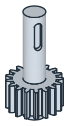
The checks
These are the span over three teeth, the clearance in the chambers, the volumes and the masses in case-hardening steel 16MnCr5 (7.85 g/cm³), to compare with your own model. Three checks follow:
The span over \(k\) teeth is measured along a tangent to the base circle, which crosses every flank at a right angle, \(W_k = m \cos\alpha\,\bigl(\pi\,(k - \tfrac{1}{2}) + z\,\mathrm{inv}\,\alpha\bigr)\), here less the two thinned flanks, \(2 \cdot 0.025 \cdot \cos\alpha\).
The tips clear the chambers of 38.5 by 0.25 all around, so nothing of the gears lies outside them.
The rotors’ volumes follow from the areas, as on the spur gear, the face times 20 and the journals, the drive rotor less what its keyseat takes.
[11]:
rb = m * z / 2 * math.cos(alpha)
chords = px.Line((-30, -rb), (30, -rb)) * face  # the tangent's pieces inside the teeth
ends = sorted(sorted((e.start.x, e.end.x)) for e in chords.edges)
middle = min(range(len(ends)), key=lambda i: abs(sum(ends[i])))
span = ends[middle + 1][1] - ends[middle - 1][0]
w = m * math.cos(alpha) * (math.pi * 2.5 + z * inv(alpha)) - 2 * 0.025 * math.cos(alpha)
print("span over 3 teeth", round(span, 6), "| formula", round(w, 6))
chambers = px.Unify([px.Circle((-17, 0), 38.5 / 2).Face(), px.Circle((17, 0), 38.5 / 2).Face()]).Face()
gears = px.Unify([face.Translated((-17, 0)), face.Translated((17, 0))])
print("outside the chambers", (gears - chambers).mass, "| tips to the chambers", round(chambers.outer.Distance(gears), 6))
journals = math.pi * 7.5**2
for name, above, less in (("idler", 9, 0.0), ("drive", 50, keyseat_volume)):
    volume = face.mass * 20 + journals * (7 + above) - less
    print(name, "rotor", round(volume, 1), "mm³ | mass", round(volume * 7.85e-6 * 1000, 1), "g")
span over 3 teeth 15.189861 | formula 15.189861
outside the chambers 0.0 | tips to the chambers 0.25
idler rotor 20367.7 mm³ | mass 159.9 g
drive rotor 27341.8 mm³ | mass 214.6 g
The rotors as STEP, for another CAD system:
[12]:
idler.WriteStep("pump_idler_rotor.step")
drive.WriteStep("pump_drive_rotor.step")
The rotors as STEP: pump_idler_rotor.step, pump_drive_rotor.step