Stepped shaft
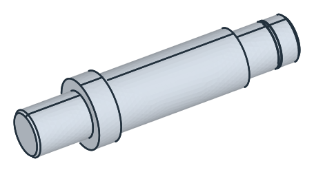
A stepped shaft carries its parts on seats of different diameters, two bearing journals at its ends, a collar that locates one bearing, and a body with a keyseat for the key of a hub. A ring groove on the right journal takes a retaining ring, and both ends are chamfered. The turned shape is a profile revolved about the axis. The keyseat is cut afterwards, from the plane tangent to the body’s top. Model the shaft from the drawing in planex2d or in any CAD system, then check its volume, mass and center of mass against the values at the end of the page. A solution in planex2d follows.

[1]:
import math
import netgen.occ as occ
import planex as px
The profile
The profile is the half section above the axis, sketched in the front plane, the plane with its normal toward the viewer, \(-y\). Its \(x\) runs along the axis and \(z\) out from it, with the origin on the axis at the left end. The outline runs along the axis to the right end, up it, back along the right journal with the groove, and down the steps of the body and the collar to the left journal. Every line is horizontal or vertical and is drawn so. With
auto_constraint={"horizontal": True, "vertical": True}, each line stays level or plumb as it is drawn, without a flag of its own.
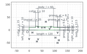
The shaft is 120 long. The left journal is 20 across and 25 long, the collar 30 across and 10 long, the body 25 across and 60 long, and the right journal 20 across. The groove, 1.3 wide and 19 across at its bottom, begins 8.7 from the right end (Figure 1):
[3]:
front = px.XZ
shaft = px.Sketch(front, auto_constraint={"horizontal": True, "vertical": True})
shaft.Move((0, 0)).Line(120, id="axis")
shaft.Turn(90).Line(10, id="right_end")  # Turn(90) turns the pen left, Turn(-90) right
shaft.Turn(90).Line(8.7, id="groove_start")
shaft.Turn(90).Line(0.5, id="groove_right")
shaft.Turn(-90).Line(1.3, id="groove")
shaft.Turn(-90).Line(0.5, id="groove_left")
shaft.Turn(90).Line(15, id="right_journal")
shaft.Turn(-90).Line(2.5, id="body_right")
shaft.Turn(90).Line(60, id="body")
shaft.Turn(-90).Line(2.5, id="collar_right")
shaft.Turn(90).Line(10, id="collar")
shaft.Turn(90).Line(5, id="collar_left")
shaft.Turn(-90).Line(25, id="left_journal")
shaft.Close(id="left_end")
shaft.Constrain("axis.start", "origin", px.Coincident)
shaft.Constrain("axis", px.Distance, 120, id="length")
for line, r in (("groove_start", 10), ("right_journal", 10), ("body", 12.5), ("collar", 15), ("left_journal", 10)):
    shaft.Constrain(line, "H", px.Distance, r, id=line + "_r")  # the radius: half the diameter
shaft.Constrain("groove", "H", px.Distance, 19 / 2, id="groove_r")
shaft.Constrain("groove_start", px.Distance, 8.7, id="groove_at")
shaft.Constrain("groove", px.Distance, 1.3, id="groove_w")
shaft.Constrain("body", px.Distance, 60, id="body_l")
shaft.Constrain("collar", px.Distance, 10, id="collar_l")
shaft.Constrain("left_journal", px.Distance, 25, id="journal_l")
print("status", shaft.status, "| degrees of freedom", shaft.dof)
status full | degrees of freedom 0
The chamfers
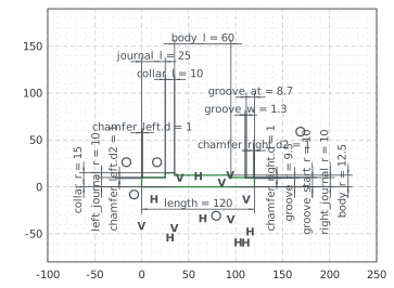
Both ends are chamfered 1 by 45°, at the corners where the end faces meet the journals. Chamfer cuts the two corners and keeps their dimensions (Figure 2):
[5]:
shaft.Chamfer(["right_end.end", "left_end.start"], 1, id=["chamfer_right", "chamfer_left"])
print("status", shaft.status, "| degrees of freedom", shaft.dof)
status full | degrees of freedom 0
The shaft
The profile’s face, taken to OpenCASCADE with ToOCCFace, is revolved a full turn about the \(x\) axis with netgen’s Revolve. By Pappus’s theorem, the volume is the profile’s area times the length of the circle that its centroid runs on (Figure 3):
[7]:
profile = shaft.Face()
solid = profile.ToOCCFace().Revolve(occ.Axis((0, 0, 0), occ.X), 360)
print("volume", round(solid.mass, 3), "| Pappus", round(2 * math.pi * profile.center[2] * profile.mass, 3))
volume 52128.421 | Pappus 52128.421
The keyseat
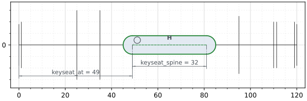
The keyseat is a slot 8 wide and 40 long with round ends, 4 deep, its left end 10 from the collar. It is sketched on the plane tangent to the body’s top, the xy plane lifted by the body’s radius of 12.5, which is px.Plane(px.XY, 12.5). On it, \(x\) runs along the axis and \(y\) across, with the axis below the origin. Slot draws the slot from its spine, 32 between the centers of its ends, and its width is the slot’s own dimension keyseat.w. The slot is pocketed 4 deep, against
the plane’s normal, down into the body (Figure 4):
[9]:
keyseat = px.Sketch(px.Plane(px.XY, 12.5))
keyseat.Move((49, 0), dir=(1, 0)).Slot(32, 8, id="keyseat")  # 32 between the centers of the ends, 8 wide
keyseat.Constrain("keyseat.spine", px.Horizontal)
keyseat.Constrain("keyseat.spine.start", "H", px.Coincident)
keyseat.Constrain("keyseat.spine.start", "V", px.Distance, 35 + 10 + 4, id="keyseat_at")  # its end 10 from the collar
keyseat.Constrain("keyseat.spine", px.Distance, 32, id="keyseat_spine")
print("status", keyseat.status, "| degrees of freedom", keyseat.dof)
solid = px.Pocket(solid, keyseat, 4)
status full | degrees of freedom 0
(a) The keyseat on the plane over the body
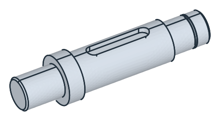
(b) The keyseat in the body
The checks
These are the volume, the mass in steel C45 (7.85 g/cm³) and the center of mass, with the origin on the axis at the left end, to compare with your own model. The revolved part follows from Pappus’s theorem. The keyseat’s floor lies 4 below the top, at 8.5 from the axis, and the slot takes from the body what lies above its floor and inside the circle of radius 12.5. That is a straight part 32 long and the two half discs at its ends. The straight part has a closed form, and the half discs are integrated numerically across the slot’s width, so the reference volume is as exact as that integral. The keyseat takes material above the axis, so the center of mass lies just below it:
[11]:
def strip(y):  # the body's height above the keyseat's floor at y across the slot
    return math.sqrt(12.5**2 - y * y) - 8.5


def segment(y):  # the area under the circle of radius 12.5 from 0 to y
    return y / 2 * math.sqrt(12.5**2 - y * y) + 12.5**2 / 2 * math.asin(y / 12.5)


straight = 32 * (2 * segment(4) - 8.5 * 8)
n = 2000
ends = sum(2 * (4 * math.cos(t)) * strip(4 * math.sin(t)) * 4 * math.cos(t) * math.pi / n
           for t in (-math.pi / 2 + math.pi * (k + 0.5) / n for k in range(n)))  # y = 4 sin t: smooth in t
reference = 2 * math.pi * profile.center[2] * profile.mass - straight - ends
c = solid.center
print("volume", round(solid.mass, 1), "mm³, reference", round(reference, 1))
print("mass", round(solid.mass * 7.85e-6, 3), "kg")
print("center of mass", round(c.x, 2), "along the axis,", round(-c.z, 3), "below it, off the plane y = 0 by", round(abs(c.y), 6))
volume 50967.0 mm³, reference 50967.0
mass 0.4 kg
center of mass 58.58 along the axis, 0.237 below it, off the plane y = 0 by 0.0
The shaft as STEP, for another CAD system:
[12]:
solid.WriteStep("stepped_shaft.step")
The shaft as STEP: stepped_shaft.step