From .CATPart file to parametric model
A sketch drawn in a CAD program carries its design intent in its constraints and dimensions. px.FromCATPart reads the sketches of a .CATPart file as planex2d constraint sketches, with their constraints, dimensions, parameters and formulas, so that a dimension changes in Python and the profile follows, with no CAD program installed. A parametric sketch can also be drawn in code, or made from a DXF or SVG drawing with its constraints found automatically. The first cell is the complete
workflow, ready to copy and run, and the section Step by step runs it in parts, with the plots one looks at along the way.
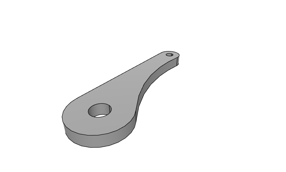
The example is a lever: a pivot boss of radius 22 with a bore of 16, an arm boss of radius 11 with a pin hole of 8, 100 apart at 15° to the horizontal, an upper flank tangent to both bosses, and a lower flank, a spline through a waist point, tangent to both. The file, lever.CATPart, is not part of these pages; any sketch of a .CATPart file reads the same way.
[2]:
import netgen.occ as occ
from ngsolve_webgpu.jupyter import Draw
import planex as px

part = px.FromCATPart("lever.CATPart", scale=1)
lever = part["sketches"]["Sketch.1"]
print(lever.status, lever.dof, lever.dimensions)

lever.Update({"Distance.2": 120, "Radius.1": 25})
print(lever.status, lever.dof, "| area", lever.Face().mass)

solid = px.Pad(lever.Face(), 10)
solid.WriteStep("lever.step")
print("volume", solid.mass, "| read back", occ.OCCGeometry("lever.step").shape.mass)
Draw(solid)
full 0 {'Distance.1': 50.0, 'Distance.2': 100.0, 'Distance.3': 8.0, 'Diameter.1': 16.0, 'Radius.1': 22.0, 'Radius.2': 11.0, 'Diameter.2': 8.0, 'Angle.1': 15.0}
full 0 | area 4380.6170609769915
volume 43806.17060975529 | read back 43806.170609766654
Step by step
Reading the part
px.FromCATPart returns a dictionary: "sketches" holds the part’s sketches by their names, and "parameters" its parameters, here none. scale=1 keeps the file’s millimeter numbers, which OpenCASCADE takes as millimeters, where the default converts them to meters. The sketch reads fully constrained, as it was saved (see CATIA V5 for what the reader takes and Files for the other readers).
[3]:
import netgen.occ as occ
from ngsolve_webgpu.jupyter import Draw
import planex as px

part = px.FromCATPart("lever.CATPart", scale=1)
print(list(part["sketches"]), "| parameters", part["parameters"])
lever = part["sketches"]["Sketch.1"]
print(lever.status, lever.dof)
['Sketch.1'] | parameters Parameters()
full 0
Finding the dimensions
The file gives its dimensions no names, so they have planex2d’s ids, numbered by kind in the file’s order. lever.dimensions lists them with their values, and in the plotly plot below, hovering over a dimension shows its id, such as Distance.2: "Line.2", px.Distance, 100 for the distance between the bosses along the center line (see Sketch plots).
[4]:
print(lever.dimensions)
lever.Plot(backend="plotly", show_constraints=True)
{'Distance.1': 50.0, 'Distance.2': 100.0, 'Distance.3': 8.0, 'Diameter.1': 16.0, 'Radius.1': 22.0, 'Radius.2': 11.0, 'Diameter.2': 8.0, 'Angle.1': 15.0}
Changing the design
Update takes new values by id, in the sketch’s millimeters: the bosses 120 apart and the pivot boss of radius 25. The flanks stay tangent, the bore and the pin hole stay concentric with their bosses, and the sketch stays fully constrained (Figure 1). A set of values can also come from a spreadsheet, one row per variant (see Design tables in a spreadsheet), and Animate steps through them (see Animating a
sketch).
[6]:
lever.Update({"Distance.2": 120, "Radius.1": 25})
print(lever.status, lever.dof, "| area", lever.Face().mass)
# px.Plot(lever)
full 0 | area 4380.6170609769915
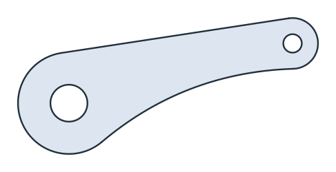
(a) As saved: Distance.2 = 100, Radius.1 = 22
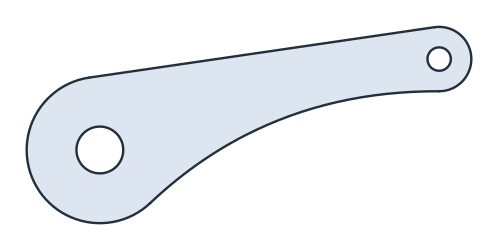
(b) Distance.2 = 120, Radius.1 = 25
The 3D part and STEP
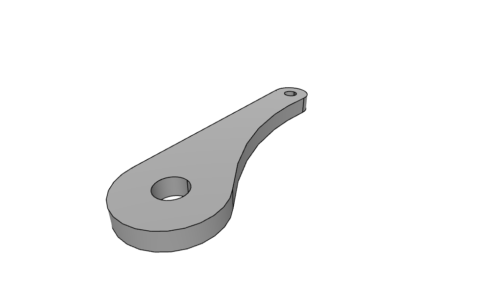
The reader takes the part’s sketches, not its 3D features, so the part is built again from the sketch: px.Pad extrudes the lever’s face 10 mm, and WriteStep writes the solid for any CAD program. The volume is the face’s area times 10, and OpenCASCADE reads the file back with the same (see Pad and Pocket and To OCC shapes).
[8]:
solid = px.Pad(lever.Face(), 10)
solid.WriteStep("lever.step")
print("volume", solid.mass, "| area × 10", lever.Face().mass * 10, "| read back",
      occ.OCCGeometry("lever.step").shape.mass)
Draw(solid)
volume 43806.17060975529 | area × 10 43806.17060976991 | read back 43806.170609766654
Where the sketch comes from
Source |
Call |
What it brings |
See |
|---|---|---|---|
A .CATPart file |
|
Constraints, dimensions, parameters, formulas |
|
A DXF or SVG drawing |
|
The geometry, its constraints found automatically |
|
Code |
|
Whatever the code draws and constrains |
Pitfalls
Units. Without
scale=1, the reader converts the file’s millimeters to meters, and the values given toUpdateare then in meters too.Ids. Dimensions without a name in the file get planex2d’s ids, numbered in the file’s order, so another file can number them differently. Names given to the dimensions or parameters in the file become their ids.
Free elements. A sketch saved with elements free reads with them free.
statusanddofsay so, andFreeMotions()shows what moves (see Fully, under- and over-constrained).What is not read. The part’s 3D features, such as pads and pockets, are not read, and one warning names them. An ellipse comes in as a fixed curve, and equidistant points, projected outlines and constraints on a spline’s tangent arrow are left out, which one warning per sketch names.
In the browser
The reader needs no other package, so the steps up to the 3D part run in the playground: a .CATPart file added with Files reads by its name, changes and plots there. The pad and the STEP file need the OpenCASCADE bindings, which the browser does not have.