Impeller
The impeller of a centrifugal pump throws the liquid outward between its blades. The liquid enters around the hub, at the inlet circle, and leaves at the rim, at the outlet circle. On this semi-open impeller, six blades stand on a back disc. Each blade is a circular arc from the inlet circle to the outlet circle, 3 thick with round ends, and the blades lose height toward the rim, from 15 at the inlet to 8 at the outlet. Seen from the blades’ side, the impeller turns clockwise, and the blades curve backward against it. As a solid, the disc and the hub are one revolved half section, and the blades are padded and then cut to a revolved contour. Model the impeller from the drawing in planex2d or in any CAD system, then check its volume, mass and center of mass against the values at the end of the page. A solution in planex2d follows.

[1]:
import math
import netgen.occ as occ
import planex as px
The disc and the hub
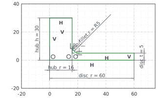
The disc and the hub are one half section, revolved about the axis. It is sketched in the front plane, the plane with its normal toward the viewer, \(-y\). Its \(x\) runs out from the axis and \(z\) along it, with the origin on the axis at the back of the disc. The outline runs out along the back, up the rim, in along the disc’s face to the hub, up the hub and back to the axis. The disc is 120 across and 5 thick, the hub 32 across and 30 high from the back. The hub meets the disc with a fillet of 5 (Figure 1):
[3]:
front = px.XZ
section = px.Sketch(front, auto_constraint={"horizontal": True, "vertical": True})
section.Move((0, 0)).Line(60, id="back")
section.Turn(90).Line(5, id="rim")  # Turn(90) turns the pen left, Turn(-90) right
section.Turn(90).Line(44, id="disc_face")
section.Turn(-90).Line(25, id="hub_side")
section.Turn(90).Line(16, id="hub_top")
section.Close(id="axis")
section.Constrain("back.start", "origin", px.Coincident)
section.Constrain("back", px.Distance, 60, id="disc_r")
section.Constrain("rim", px.Distance, 5, id="disc_t")
section.Constrain("hub_side", "V", px.Distance, 16, id="hub_r")
section.Constrain("hub_top", "H", px.Distance, 30, id="hub_h")
section.Fillet(["disc_face.end"], 5, id=["hub_fillet"])
print("status", section.status, "| degrees of freedom", section.dof)
status full | degrees of freedom 0
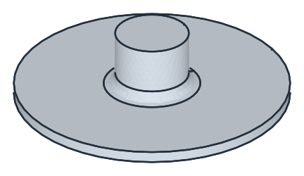
The section’s face, taken to OpenCASCADE with ToOCCFace, is revolved a full turn about the \(z\) axis. By Pappus’s theorem, the volume is the face’s area times the length of the circle that its centroid runs on (Figure 2):
[5]:
face = section.Face()
body = face.ToOCCFace().Revolve(occ.Axis((0, 0, 0), occ.Z), 360)
print("volume", round(body.mass, 3), "| Pappus", round(2 * math.pi * face.center[0] * face.mass, 3))
volume 77231.862 | Pappus 77231.862
The blades
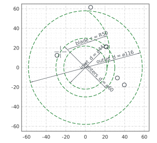
The blades are sketched on the plane of the disc’s face, the xy plane lifted by 5. Three construction circles carry them: the inlet circle of 44 and the outlet circle of 116, between which the blades run, and a circle of 60 on which the centers of their arcs lie. The first blade’s center line is an arc of radius 50 from the inlet circle, where it starts on the \(x\) axis, to the outlet circle, drawn roughly and placed by the constraints (Figure 3):
[7]:
blades = px.Sketch(px.Plane(px.XY, 5))
for ref, d in (("inlet", 44), ("outlet", 116), ("centers", 60)):
    blades.Circle(d / 2, id=ref, construction=True)
    blades.Constrain(ref + ".center", "origin", px.Coincident)
    blades.Constrain(ref, px.Diameter, d, id=ref + "_d")
blades.Move((22, 0)).Arc((2, 58), 50, id="blade", construction=True)  # from the pen to the point, radius 50
blades.Constrain("blade.start", "inlet", px.Coincident)  # a point on a circle
blades.Constrain("blade.start", "H", px.Coincident)
blades.Constrain("blade.end", "outlet", px.Coincident)
blades.Constrain("blade.center", "centers", px.Coincident)
blades.Constrain("blade", px.Radius, 50, id="blade_r")
print("status", blades.status, "| degrees of freedom", blades.dof)
status full | degrees of freedom 0
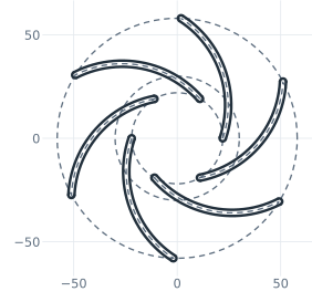
CircularPattern repeats the center line around the axis, six in all, 60° apart. Offset then turns each center line into a blade, 1.5 to each side with round ends. An offset of a construction line is construction too, so each blade is set to be drawn (Figure 4):
[9]:
blades.CircularPattern("blade", "origin", 6, id="lines")  # the copies lines.1.blade to lines.5.blade
lines = ["blade"] + [f"lines.{k}.blade" for k in range(1, 6)]
for k, line in enumerate(lines):
    blades.Offset(line, 1.5, id=f"vane_{k}")
    blades(f"vane_{k}").construction = False
print("status", blades.status, "| degrees of freedom", blades.dof)
status full | degrees of freedom 0
The blades’ contour
The blades’ tips follow a contour in the half section. It runs 20 above the back, 15 above the disc’s face, out to the inlet circle, and from there in a straight line down to 13 above the back at the outlet circle, 8 above the face. Revolved about the axis, the region under the contour is an envelope. The blades are padded 20 from the disc’s face, higher than they will be, and * keeps what lies inside the envelope (Figure 5):
[11]:
contour = px.Sketch(front, auto_constraint={"horizontal": True, "vertical": True})
contour.Move((0, 0)).Line(62, id="base")
contour.Turn(90).Line(12, id="outer")
contour.Line((22, 20), id="tip_line")
contour.Line((0, 20), id="inlet_top")
contour.Close()
contour.Vertex("outlet_tip", (58, 13))
contour.Constrain("base.start", "origin", px.Coincident)
contour.Constrain("base", px.Distance, 62)
contour.Constrain("inlet_top", "H", px.Distance, 20, id="inlet_h")
contour.Constrain("tip_line.end", "V", px.Distance, 22, id="inlet_r")
contour.Constrain("outlet_tip", "tip_line", px.Coincident)
contour.Constrain("outlet_tip", "V", px.Distance, 58, id="outlet_r")
contour.Constrain("outlet_tip", "H", px.Distance, 13, id="outlet_h")
print("status", contour.status, "| degrees of freedom", contour.dof)
envelope = contour.Face().ToOCCFace().Revolve(occ.Axis((0, 0, 0), occ.Z), 360)
vanes = px.Pad(blades, 20) * envelope
impeller = body + vanes
status full | degrees of freedom 0
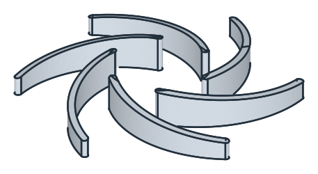
(a) The blades cut to the revolved contour
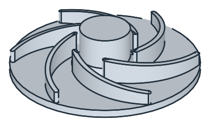
(b) On the disc
The bore
The bore, 16 across, and the keyway, 5 wide and 18.3 deep from the far side of the bore, are pocketed from the hub’s top. The bore goes to the last face it crosses, and the keyway 30 deep, through the hub (Figure 6):
[13]:
bore = px.QuickSketch(impeller.faces.Max(occ.Z)).Circle(8)
impeller = px.Pocket(impeller, bore, until=px.last)
keyway = px.QuickSketch(impeller.faces.Max(occ.Z)).Move((-2.5, 0)).Rectangle(5, 18.3 - 8)  # from the axis to its top
impeller = px.Pocket(impeller, keyway, 30)
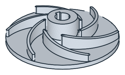
The checks
These are the volume, the mass in bronze CuSn10 (8.7 g/cm³) and the center of mass, with the origin on the axis at the back of the disc, to compare with your own model. The length of a blade’s center line checks the sketch. The line runs between the angles at its center that the law of cosines gives for the inlet and the outlet circle, in the triangle of the axis, the arc’s center 30 from it, and a point of the arc 50 from the center. The keyway takes material on one side, so the center of mass lies just off the axis:
[15]:
def angle(rho):  # at the arc's center, between the axis and the arc's point at the radius rho
    return math.acos((50**2 + 30**2 - rho**2) / (2 * 50 * 30))


c = impeller.center
print("blade length", round(blades.Measure("blade")["length"], 6), "| exact", round(50 * (angle(58) - angle(22)), 6))
print("volume", round(impeller.mass, 1), "mm³")
print("mass", round(impeller.mass * 8.7e-6, 3), "kg")
print("center of mass", round(c.z, 2), "above the back,", round(-c.y, 3), "off the axis, away from the keyway")
blade length 66.079859 | exact 66.079859
volume 85151.4 mm³
mass 0.741 kg
center of mass 6.56 above the back, 0.039 off the axis, away from the keyway
The impeller as STEP, for another CAD system:
[16]:
impeller.WriteStep("impeller.step")
The impeller as STEP: impeller.step