Bell crank
A bell crank turns a pull in one direction into a pull in another. It pivots on its hub, and its two arms, at an angle to each other, carry the rods at their bosses. As a sketch, it is one chain of lines and tangent arcs around the hub, the two bosses and the corner between the arms. Model the bell crank from the drawing in planex2d or in any CAD system, then check its area and centroid against the values at the end of the page. A solution in planex2d follows.

[1]:
import math
import planex as px
The outline
The outline is one chain, drawn roughly from the start at the origin. It runs a quarter arc around the hub, a line out along the first arm, a half circle around its boss, a line back, a small arc the other way for the corner between the arms, a line out along the second arm and a half circle around its boss. Close() closes the chain with a line back to the start. With auto_constraint=True, every joint of the chain becomes a tangency, the closing line’s included, so the outline keeps its
shape when the dimensions move it.
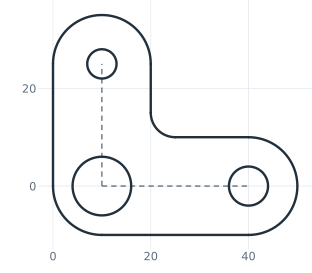
The pieces get their ids in the order they are drawn, the arcs Arc.1 to Arc.4 (the hub, the first boss, the corner and the second boss) and the lines Line.1 to Line.4. The interactive plot below shows a piece’s id when the mouse is over it:
[3]:
crank = px.Sketch(auto_constraint=True)
crank.Move((0, 0), dir=(0, -1)).Arc(10, 90).Line(30).Arc(10, 180).Line(15).Arc(5, -90).Line(10).Arc(10, 180).Close()
crank.Plot(backend="plotly")
The holes and the center lines
The holes go into the centers of the hub and the bosses, with concentric=. The hub’s bore is fixed with px.Fix where it is drawn, its center at (10, 0) and its diameter 12, and it holds the sketch in place. The arms’ center lines are construction lines from the hub’s center to the center of each boss, the first one horizontal. crank("left.center") is the bore’s center as a point (Figure 1).
[4]:
crank.Circle(6 / 2, concentric="Arc.4", id="top")
crank.Circle(8 / 2, concentric="Arc.2", id="right")
crank.Circle(12 / 2, px.Fix, concentric="Arc.1", id="left")
crank.Line(crank("left.center"), crank("right.center"), px.Horizontal, construction=True, id="c_bottom")
crank.Line(crank("left.center"), crank("top.center"), construction=True, id="c_left");
The dimensions
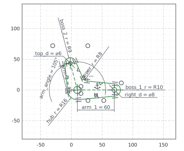
The arms are 60 and 45 long from center to center, and their center lines make an angle of 105°, set with px.Angle. The flanks of each arm are mirrored about its center line with px.SymmetricCarriers, which mirrors their lines, not their ends. The radii of the hub, the bosses and the corner and the diameters of the holes complete the sketch. Nothing in it is left free (Figure 2):
[6]:
crank.Constrain("c_bottom", "c_left", px.Angle, 105, id="arm_angle")  # in degrees
crank.Constrain("Arc.1", px.Radius, 16, id="hub_r")
crank.Constrain("Arc.2", px.Radius, 10, id="boss_1_r")
crank.Constrain("Arc.3", px.Radius, 8, id="corner_r")
crank.Constrain("Arc.4", px.Radius, 9, id="boss_2_r")
crank.Constrain("Line.3", "Line.4", "c_left", px.SymmetricCarriers)
crank.Constrain("Line.1", "Line.2", "c_bottom", px.SymmetricCarriers)
crank.Constrain("c_bottom", px.Distance, 60, id="arm_1")
crank.Constrain("c_left", px.Distance, 45, id="arm_2")
crank.Constrain("top", px.Diameter, 6, id="top_d")
crank.Constrain("right", px.Diameter, 8, id="right_d")
print("status", crank.status, "| degrees of freedom", crank.dof)
status full | degrees of freedom 0
The checks
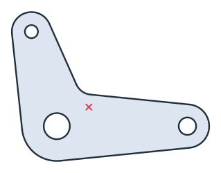
These are the area and the centroid of the bell crank, measured from the hub’s center with the first arm along x, to compare with your own model (Figure 3):
[8]:
face = crank.Face()
hub = crank.Location("left.center")
c = face.center
print("area", round(face.mass, 2), "mm²")
print("centroid from the hub's center", tuple(round(v, 2) for v in (c[0] - hub[0], c[1] - hub[1])))
area 2788.63 mm²
centroid from the hub's center (14.73, 8.77)
The bell crank as DXF in millimeters, for another CAD system or a laser cutter:
[10]:
crank.WriteDXF("bell_crank.dxf", unit=px.mm, scale=1) # scale=1: the numbers as they are
The bell crank as DXF: bell_crank.dxf