From sketch to dimensioned drawing
A constraint sketch already holds the dimensions of a part, so planex2d draws them as a dimensioned drawing, puts the drawing on a sheet with a frame and a title block, and writes it as PDF, DXF or SVG. When a dimension changes, the drawing follows. The sketch can be drawn in code, read from a .CATPart file, or made from a DXF or SVG drawing with its constraints found automatically, and views of OpenCASCADE solids go on the same sheets. The first cell is the complete workflow, ready to copy and run, and the section Step by step runs it in parts, with the plots one looks at along the way.
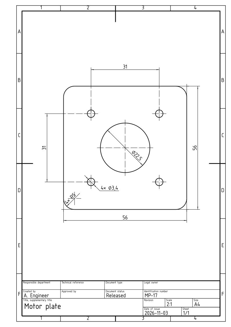
The example is a mounting plate for a NEMA 17 stepper motor, 56 × 56 mm with corners of radius 5, a bore of 22.5 for the motor’s pilot and four holes of 3.4 for M3 screws on the motor’s square of 31 mm.
[1]:
import planex as px

plate = px.Sketch(auto_constraint=True)
plate.RectangleC(56, 56, id="plate")
plate.Constrain("plate.center", "origin", px.Coincident)
plate.Constrain("plate.Line.1", px.Horizontal)
plate.Constrain("plate.Line.1", px.Distance, 56, id="width")
plate.Constrain("plate.Line.2", px.Distance, 56, id="height")
plate.Fillet(["plate.Line.1.start", "plate.Line.2.start", "plate.Line.3.start", "plate.Line.4.start"], 5,
             id=["corner_1", "corner_2", "corner_3", "corner_4"])
for k in (2, 3, 4):
    plate.Remove(f"corner_{k}.r")
    plate.Constrain(f"corner_{k}", "corner_1", px.Equal)
plate.Circle(11.25, id="pilot")
plate.Constrain("pilot.center", "origin", px.Coincident)
plate.Constrain("pilot", px.Diameter, 22.5, id="pilot_d")
plate.Circle(1.7, center=(-15.5, -15.5), id="hole")
plate.Constrain("hole", px.Diameter, 3.4, id="hole_d")
plate.Constrain("hole.center", "V", px.Distance, 15.5, id="hole_x")
plate.Constrain("hole.center", "H", px.Distance, 15.5, id="hole_y")
plate.LinearPattern(["hole"], px.H, 2, 31, dir2=px.V, count2=2, spacing2=31, id="holes")
print("status", plate.status, "| degrees of freedom", plate.dof)

dw = px.Drawing(plate, unit=px.mm).Hide("hole_x").Hide("hole_y")
dw.Measure((-15.5, 15.5), (15.5, 15.5), offset=20).Measure((-15.5, -15.5), (-15.5, 15.5), offset=20)
sheet = px.Sheet(dw, frame=True)
sheet.Title(title="Motor plate", number="MP-17", author="A. Engineer", status="Released")
sheet.WritePDF("motor_plate.pdf")
sheet.WriteDXF("motor_plate.dxf")
sheet
status full | degrees of freedom 0
[1]:
Step by step
Sketching the part
The plate is a constraint sketch drawn in millimeter numbers. RectangleC draws it around the origin, and its width and height are named dimensions. The four corners are filleted, and the other three radii are made equal to the first, so one number sets all four. The pilot bore sits on the origin, and the screw holes are one hole placed 15.5 from the center lines and a LinearPattern of 2 × 2 copies, 31 apart. The sketch is fully constrained, with no degree of freedom left, which is what a
complete drawing needs. In the plot below, hovering over an element or a constraint’s sign shows its id and what it is. See Constraint sketches, Fillets and chamfers and Symmetry and patterns for details.
[2]:
import planex as px

plate = px.Sketch(auto_constraint=True)
plate.RectangleC(56, 56, id="plate")
plate.Constrain("plate.center", "origin", px.Coincident)
plate.Constrain("plate.Line.1", px.Horizontal)
plate.Constrain("plate.Line.1", px.Distance, 56, id="width")
plate.Constrain("plate.Line.2", px.Distance, 56, id="height")
plate.Fillet(["plate.Line.1.start", "plate.Line.2.start", "plate.Line.3.start", "plate.Line.4.start"], 5,
             id=["corner_1", "corner_2", "corner_3", "corner_4"])
for k in (2, 3, 4):
    plate.Remove(f"corner_{k}.r")
    plate.Constrain(f"corner_{k}", "corner_1", px.Equal)
plate.Circle(11.25, id="pilot")
plate.Constrain("pilot.center", "origin", px.Coincident)
plate.Constrain("pilot", px.Diameter, 22.5, id="pilot_d")
plate.Circle(1.7, center=(-15.5, -15.5), id="hole")
plate.Constrain("hole", px.Diameter, 3.4, id="hole_d")
plate.Constrain("hole.center", "V", px.Distance, 15.5, id="hole_x")
plate.Constrain("hole.center", "H", px.Distance, 15.5, id="hole_y")
plate.LinearPattern(["hole"], px.H, 2, 31, dir2=px.V, count2=2, spacing2=31, id="holes")
print("status", plate.status, "| degrees of freedom", plate.dof)
plate.Plot(backend="plotly", show_constraints=True)
status full | degrees of freedom 0
The drawing
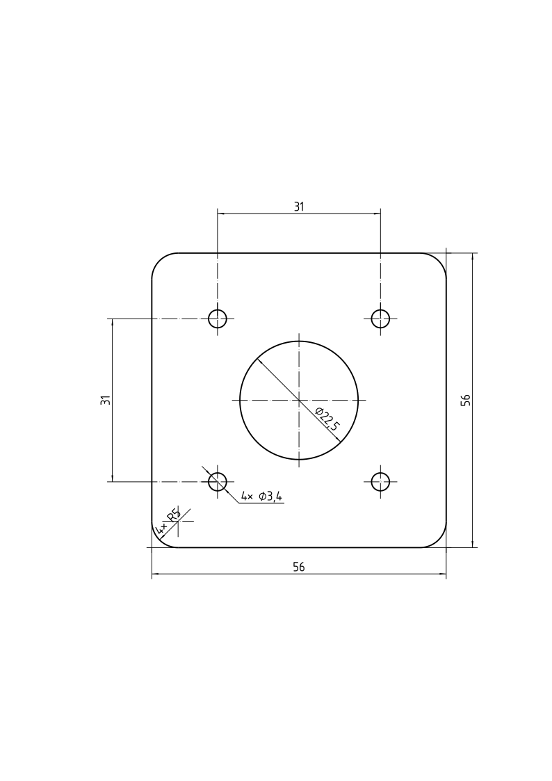
px.Drawing lays out the sketch’s dimensions as a drawing, with dimension lines, center lines and values in millimeters, since unit=px.mm says that the sketch is drawn in millimeter numbers. Equal radii and diameters are grouped as “4× R5” and “4× ⌀3,4”. The screw holes are better dimensioned by their square of 31, the number on the motor’s data sheet, than by the 15.5 that place the first one, so Hide takes those two out and Measure draws the 31 in each direction, 20 from the
holes. See A dimensioned drawing and Placing dimensions for details.
[3]:
dw = px.Drawing(plate, unit=px.mm).Hide("hole_x").Hide("hole_y")
dw.Measure((-15.5, 15.5), (15.5, 15.5), offset=20).Measure((-15.5, -15.5), (-15.5, 15.5), offset=20)
dw
[3]:
The sheet
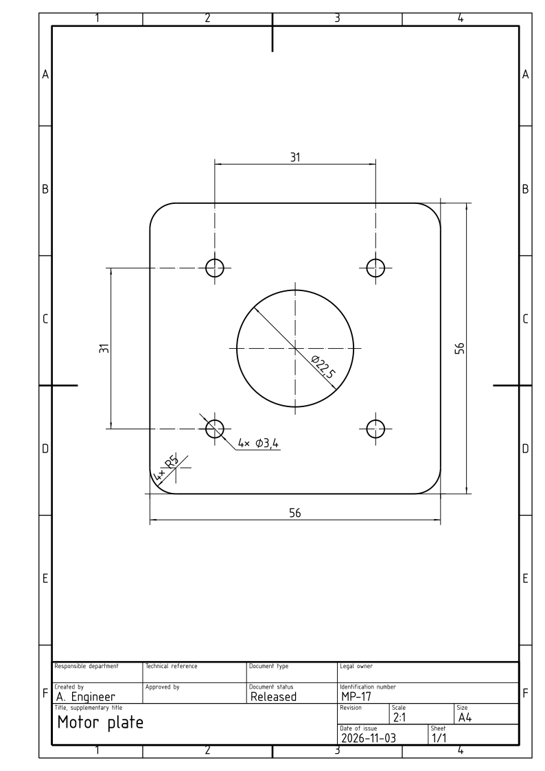
px.Sheet puts the drawing on an A4 sheet at the largest standard scale that fits, 2:1 here, and frame=True adds the frame with its grid. Title fills planex2d’s title block with the title, the drawing number, the author and the status. See Views and sheets and Title blocks and files for other views on one sheet, landscape sheets and a company’s own title block.
[4]:
sheet = px.Sheet(dw, frame=True)
sheet.Title(title="Motor plate", number="MP-17", author="A. Engineer", status="Released")
sheet
[4]:
Writing the files
WritePDF writes the sheet at true scale, to print at 100 %, and WriteDXF writes it with its dimensions as DXF dimension entities, for another CAD program. The files are motor_plate.pdf and motor_plate.dxf, and WriteSVG writes the same sheet as SVG.
[5]:
sheet.WritePDF("motor_plate.pdf")
sheet.WriteDXF("motor_plate.dxf")
Changing the design
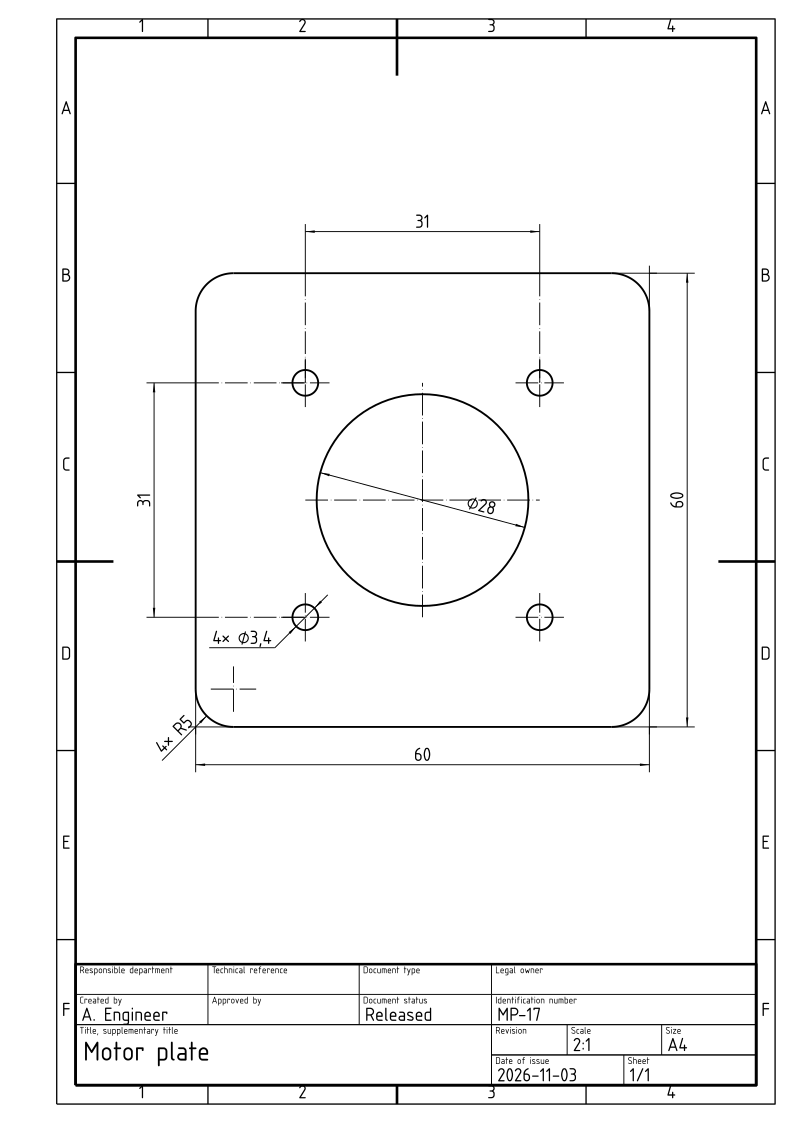
The drawing follows the sketch. After a change of the sketch’s dimensions, here a bore of 28 for a larger pilot and a plate of 60 × 60, Update solves the sketch again and dw.Update() redraws the drawing on the same sheet:
[6]:
plate.Update({"pilot_d": 28, "width": 60, "height": 60})
dw.Update()
sheet
[6]:
Where the sketch comes from
Source |
Call |
See |
|---|---|---|
Code |
|
|
A .CATPart file |
|
|
A DXF or SVG drawing |
|
|
An OpenCASCADE solid |
|
Pitfalls
Units.
unit=px.mmis for a sketch drawn in millimeter numbers. A sketch from a reader is in meters, which is the default, and the drawing writes its values in millimeters either way.Free sketches. The drawing shows the sketch’s dimensions and nothing else, so a sketch that is not fully constrained gives a drawing with dimensions missing.
statusanddofsay whether anything is free.Measured dimensions.
Measuretakes two points, not references, so a measured dimension stays where it is when the sketch changes. The dimensions from the sketch’s constraints follow it.The scale. The sheet takes the largest standard scale that fits, and a part wider than tall fits better with
landscape=True.