Sections
px.Drawing(part, plane, section=True) cuts the solid at the plane and draws the material behind it, seen along the plane. The cut faces are hatched, and the hidden edges are left out. A section is named by its letters, view_name="Section view A-A" or "A-A", and dw.Section(section) marks the cut on the view it is taken from:
the cutting line across the part, narrow, long-dashed and dotted, wide at its ends;
an arrow at each end that points the way the section is seen, with the section’s letter.
[1]:
import math

import netgen.occ as occ
import planex as px
The bearing plate cut through its bore
The example is the bearing plate with its hub from Views of solids:
[3]:
part = px.Pad(plate, 10)
top = part.faces.Max(occ.Z)
part = part + px.Pad(px.QuickSketch(top).Circle((0, 0), 24).Circle((0, 0), 20), 15)
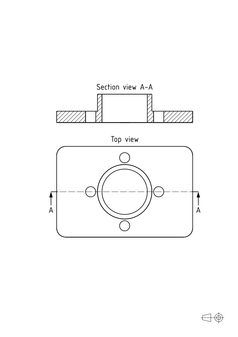
The section A-A lies in the front plane, through the axis of the bore and two of the bolt holes. It shows the plate and the wall of the hub in section, and the bolt holes and the bore as gaps in it. It takes the place of the front view, and on the top view, Section marks where it is cut:
[4]:
section = px.Drawing(part, px.Front, section=True, view_name="Section view A-A", unit=px.mm)
top_view = px.Drawing(part, px.Top, unit=px.mm)
top_view.Section(section)
px.Sheet(section, top_view)
[4]:
A section at the height of the channels
The example is the block of the exercise Manifold block, built as on that page. It is 70 × 50 × 40, with three ports, P in front, A on the top and B on the right, joined by channels drilled inside, and two mounting holes from the top. The channels from P and from B run 20 above the base, and only a section at that height shows how they meet.
The section A-A cuts the block at \(z = 20\) and is seen from above, a px.Plane with its origin at that height and its normal up. The mounting holes run through the cut, so the section carries the dimensions of their sketch on the top face at their true lengths. Hide leaves out the second hole’s distance from the left edge, which the first hole’s already gives, and Place puts the holes’ diameter and that of port P on leaders, so that their values stay clear of the hatching and of
the port’s circle. The section is no standard view, so Add places it below the front view, and Section marks the cut on the front view:
[6]:
section = px.Drawing(block, px.Plane(origin=(0, 0, 20), normal=(0, 0, 1)), section=True, view_name="A-A", unit=px.mm)
section.Add(holes).Hide("Distance.1").Place("hole_d", "ne", leader=True)
front_view = px.Drawing(block, px.Front, unit=px.mm).Add(p).Place("spot_d", "se", leader=True)
front_view.Section(section)
sheet = px.Sheet(front_view)
sheet.Add(section, at=(0, -90))
sheet
[6]:
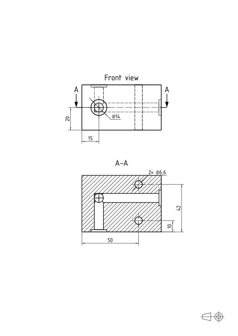
The section shows the channels from P and B meeting the channel down from A. What the drilling takes out of the block is therefore one passage, besides the two mounting holes:
[7]:
taken = occ.Box(occ.Pnt(0, 0, 0), occ.Pnt(70, 50, 40)) - block
print(len(taken.solids), "pieces drilled out")
3 pieces drilled out
A turned part in full section
The example is the slip-on flange of the exercise Pipe flange, built as on that page. It is a turned part around a bore of 49, a plate of 130 and 16 thick with a hub of 70 and 12 long behind it and a raised face of 78 and 2 high in front, with four bolt holes of 18 on a bolt circle of 100. A turned part is drawn in a full section through its axis, here the front plane, so that its profile shows on both sides of the axis.
Its diameters are no dimensions of a sketch on that plane, so Measure writes each as a length across the axis with “⌀” in front, and Axis draws the axis (see Center lines and axes). The top view carries the bolt holes’ sketch. Hide leaves out the first hole’s coordinates, which the rule that puts it at 45° adds as reference dimensions, and the bolt circle’s diameter goes on a leader:
[9]:
section = px.Drawing(flange, px.Front, section=True, unit=px.mm).Axis((0, -4), (0, 34))
section.Measure((-65, 12), (65, 12), value="⌀130", offset=36).Measure((-35, 0), (35, 0), value="⌀70", offset=12)
section.Measure((-24.5, 30), (24.5, 30), value="⌀49", offset=6)
section.Measure((-39, 30), (39, 30), value="⌀78", offset=14)
section.Measure((65, 0), (65, 12), offset=9).Measure((65, 12), (65, 28), offset=9)
section.Measure((39, 0), (39, 30), offset=47)
top_view = px.Drawing(flange, px.Top, hidden=False, unit=px.mm).Add(holes).Hide("Reference.1", "Reference.2")
top_view.Place("bolt_circle_d", 120, leader=True)
px.Sheet(section, top_view)
[9]:
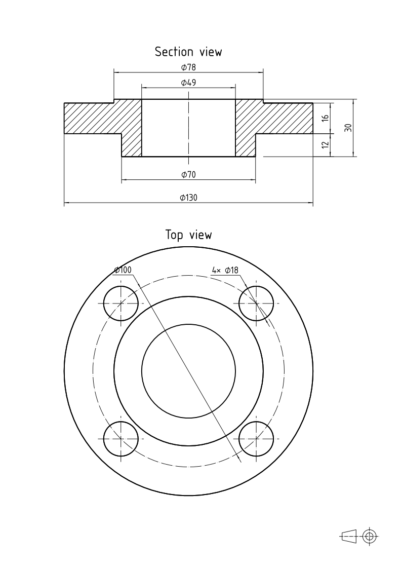
The section is the profile of three rings, the hub, the plate and the raised face, and the volume is theirs less the bolt holes through the plate:
[10]:
exact = math.pi * ((35**2 - 24.5**2) * 12 + (65**2 - 24.5**2) * 16 + (39**2 - 24.5**2) * 2 - 4 * 9**2 * 16)
print("volume", flange.mass, "exact", exact)
volume 195251.55421693242 exact 195251.55421693245
See Views of solids for views without a cut, and Views and sheets for placing views on a sheet.