Impeller with twisted blades
The blades of the impeller are the same at every height. In a real pump, the liquid meets a blade at a different angle near the hub than near the tip, and the blade twists to follow it. Here each blade is given by two sections. At the hub, 5 above the back, it is an arc of radius 50 from the inlet circle of 44. At the top, 25 higher, it is an arc of radius 40 from a circle of 70. Both end at the same point of the outlet circle, so the blade’s outlet edge stays parallel to the axis while its inlet edge leans. A loft through the two sections gives the twisted blade, the multi-section solid of other CAD systems. The blades are cut to the shroud’s contour, a revolved arc, and stand on a hub whose contour curves into the back disc. Model the impeller from the drawing in planex2d or in any CAD system, then check its volume, mass and center of mass against the values at the end of the page. A solution in planex2d follows.

[1]:
import math
import netgen.occ as occ
import planex as px
The hub
The back disc and the hub are one half section, revolved about the axis, as on the impeller. It is sketched in the front plane, the plane with its normal toward the viewer, \(-y\), with \(x\) out from the axis, \(z\) along it and the origin on the axis at the back. The disc is 120 across and 5 thick, the hub 32 across and 40 high, and the hub’s contour curves into the disc’s face with a radius of 14 (Figure 1):
[3]:
front = px.XZ
section = px.Sketch(front, auto_constraint={"horizontal": True, "vertical": True})
section.Move((0, 0)).Line(60, id="back")
section.Turn(90).Line(5, id="rim")  # Turn(90) turns the pen left, Turn(-90) right
section.Turn(90).Line(44, id="disc_face")
section.Turn(-90).Line(35, id="hub_side")
section.Turn(90).Line(16, id="hub_top")
section.Close(id="axis")
section.Constrain("back.start", "origin", px.Coincident)
section.Constrain("back", px.Distance, 60, id="disc_r")
section.Constrain("rim", px.Distance, 5, id="disc_t")
section.Constrain("hub_side", "V", px.Distance, 16, id="hub_r")
section.Constrain("hub_top", "H", px.Distance, 40, id="hub_h")
section.Fillet(["disc_face.end"], 14, id=["hub_contour"])
face = section.Face()
body = face.ToOCCFace().Revolve(occ.Axis((0, 0, 0), occ.Z), 360)
print("status", section.status, "| degrees of freedom", section.dof)
print("volume", round(body.mass, 3), "| Pappus", round(2 * math.pi * face.center[0] * face.mass, 3))
status full | degrees of freedom 0
volume 89752.321 | Pappus 89752.321
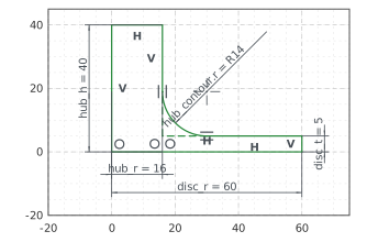
(a) The half section
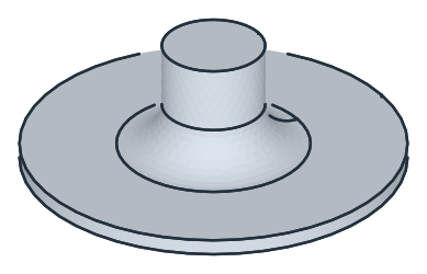
(b) Revolved
The blade’s sections
blade_section sketches one section on the xy plane lifted to the height \(z\). The blade’s center line is an arc of the given radius from its inlet circle, where it starts on the \(x\) axis, to a given point, and the blade is 3 thick around it, the center line offset by 1.5 to each side with round ends. The hub’s section, at 5, has its arc’s center on a circle of 60, as on the impeller. Its end on the outlet circle of 116 is where the top section ends too, and a
point fixed there ends the top section’s center line, at 30 (Figure 2):
[5]:
def blade_section(z, inlet_d, radius):
    sk = px.Sketch(px.Plane(px.XY, z))
    sk.Circle(inlet_d / 2, id="inlet", construction=True)
    sk.Constrain("inlet.center", "origin", px.Coincident)
    sk.Constrain("inlet", px.Diameter, inlet_d, id="inlet_d")
    sk.Move((inlet_d / 2, 0)).Arc((2, 58), radius, id="line", construction=True)  # roughly to the outlet point
    sk.Constrain("line.start", "inlet", px.Coincident)
    sk.Constrain("line.start", "H", px.Coincident)
    sk.Constrain("line", px.Radius, radius, id="line_r")
    return sk


low = blade_section(5, 44, 50)
low.Circle(116 / 2, id="outlet", construction=True)
low.Circle(60 / 2, id="centers", construction=True)
for ref, d in (("outlet", 116), ("centers", 60)):
    low.Constrain(ref + ".center", "origin", px.Coincident)
    low.Constrain(ref, px.Diameter, d, id=ref + "_d")
low.Constrain("line.end", "outlet", px.Coincident)
low.Constrain("line.center", "centers", px.Coincident)
outlet = low.Location("line.end")[:2]  # the point where both sections end

high = blade_section(30, 70, 40)
high.Vertex("outlet_point", outlet)
high.Constrain("outlet_point", px.Fix)
high.Constrain("line.end", "outlet_point", px.Coincident)
for sk in (low, high):
    sk.Offset("line", 1.5, id="blade")
    sk("blade").construction = False
    print("status", sk.status, "| degrees of freedom", sk.dof)
print("outlet point", tuple(round(v, 4) for v in outlet), "at", round(math.degrees(math.atan2(outlet[1], outlet[0])), 3), "°")
status full | degrees of freedom 0
status full | degrees of freedom 0
outlet point (1.8441, 57.9707) at 88.178 °
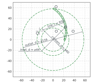
(a) The section at the hub, z = 5
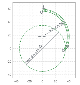
(b) The section at the top, z = 30
The twisted blades
occ.ThruSections lofts a solid through the two sections’ wires. Each has the same four edges, the two sides and the two round ends, and the loft joins them one by one. Six copies of the blade turned about the axis by 60° each make the set (Figure 3):
[7]:
blade = occ.ThruSections([low.ToOCCWire(), high.ToOCCWire()], solid=True)
blades = blade
for k in range(1, 6):
    blades = blades + blade.Rotate(occ.Axis((0, 0, 0), occ.Z), 60 * k)  # a turned copy
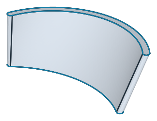
(a) One blade lofted through its two sections
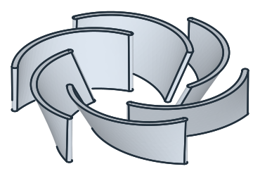
(b) Six blades
The shroud’s contour
The blades’ tips follow the shroud’s contour in the half section. It runs 30 above the back out to a radius of 35, the top section’s inlet, and then along an arc of radius 30 tangent to it down toward the rim. Revolved about the axis, the region under the contour is an envelope, and * cuts the blades to it. On the hub, they make the impeller (Figure 4):
[9]:
contour = px.Sketch(front, auto_constraint={"horizontal": True, "vertical": True})
contour.Move((0, 0)).Line(62, id="base")
contour.Turn(90).Line(12, id="outer")
contour.Arc((35, 30), 30, id="shroud")  # roughly, to the top section's inlet
contour.Line((0, 30), id="top")
contour.Close()
contour.Constrain("base.start", "origin", px.Coincident)
contour.Constrain("base", px.Distance, 62)
contour.Constrain("top", "H", px.Distance, 30, id="top_h")
contour.Constrain("top.start", "V", px.Distance, 35, id="top_r")
contour.Constrain("shroud", px.Radius, 30, id="shroud_r")
contour.Constrain("shroud", "top", px.Tangent)
print("status", contour.status, "| degrees of freedom", contour.dof)
envelope = contour.Face().ToOCCFace().Revolve(occ.Axis((0, 0, 0), occ.Z), 360)
impeller = body + blades * envelope
status full | degrees of freedom 0
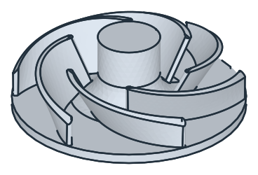
The bore
The bore is 16 across, and the keyway is 5 wide and 18.3 deep from the far side of the bore. Both are pocketed from the hub’s top, the keyway 40 deep, through the hub (Figure 5):
[11]:
bore = px.QuickSketch(impeller.faces.Max(occ.Z)).Circle(16 / 2)
impeller = px.Pocket(impeller, bore, until=px.last)
keyway = px.QuickSketch(impeller.faces.Max(occ.Z)).Move((-2.5, 0)).Rectangle(5, 18.3 - 8)  # from the axis to its top
impeller = px.Pocket(impeller, keyway, 40)
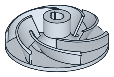
The checks
These are the volume, the mass in bronze CuSn10 (8.7 g/cm³) and the center of mass, with the origin on the axis at the back of the disc, to compare with your own model. One blade’s loft, before the cut, checks the twist. A loft through two sections joins them linearly, so its cross-section’s area is a quadratic function of the height, and Simpson’s rule gives its volume exactly from the sections’ areas at its ends and in its middle, \(\tfrac{h}{6}\,(A_\mathrm{hub} + 4 A_\mathrm{middle} + A_\mathrm{top})\) over its height of 25:
[13]:
middle = px.Intersect3d(px.Plane(px.XY, 17.5), blade).mass  # the loft's section at mid height
simpson = 25 / 6 * (low.Face().mass + 4 * middle + high.Face().mass)
c = impeller.center
print("one blade's loft", round(blade.mass, 3), "mm³, Simpson", round(simpson, 3))
print("volume", round(impeller.mass, 1), "mm³")
print("mass", round(impeller.mass * 8.7e-6, 3), "kg")
print("center of mass", round(c.z, 2), "above the back,", round(-c.y, 3), "off the axis, away from the keyway")
one blade's loft 5551.338 mm³, Simpson 5551.338
volume 108387.1 mm³
mass 0.943 kg
center of mass 9.98 above the back, 0.041 off the axis, away from the keyway
The impeller as STEP, for another CAD system:
[14]:
impeller.WriteStep("twisted_impeller.step")
The impeller as STEP: twisted_impeller.step