Inset-fed patch antenna for 2.45 GHz
The example is a rectangular microstrip patch for 2.45 GHz on FR-4 (εr = 4.4, 1.6 mm thick), fed by a 50 Ω line that reaches into the patch between two notches. The dimensions come from the classic design formulas. The copper consists of three rectangles and two notches, and the board is a substrate box with the copper glued onto its top. Lengths are in mm.

[1]:
import math
import netgen.occ as occ
import ngsolve as ngs
from ngsolve.webgui import Draw
import planex as px
Design
The design formulas give the width and length of the patch with the fringing correction, the 50 Ω line width (Wheeler), and the inset depth from the edge resistance of a single radiating slot (the classic estimate without mutual coupling), for the frequency f = 2.45 GHz, the permittivity er = 4.4 and the thickness h = 1.6:
[3]:
f = 2.45e9
er = 4.4
h = 1.6
lam = 299792458.0 / f * 1e3
W = lam / 2 * math.sqrt(2 / (er + 1))
eeff = (er + 1) / 2 + (er - 1) / 2 / math.sqrt(1 + 12 * h / W)
dL = 0.412 * h * (eeff + 0.3) * (W / h + 0.264) / ((eeff - 0.258) * (W / h + 0.8))
L = lam / (2 * math.sqrt(eeff)) - 2 * dL
A = 50 / 60 * math.sqrt((er + 1) / 2) + (er - 1) / (er + 1) * (0.23 + 0.11 / er)
wf = 8 * math.exp(A) / (math.exp(2 * A) - 2) * h
R_edge = 90 / (2 * (W / lam) ** 2)
y0 = L / math.pi * math.acos(math.sqrt(50 / R_edge))
print("patch", round(W, 2), "x", round(L, 2), "feed", round(wf, 2), "wide, inset", round(y0, 2), "deep")
print("edge resistance", round(R_edge), "Ohm")
patch 37.23 x 28.81 feed 3.06 wide, inset 11.41 deep
edge resistance 486 Ohm
The copper
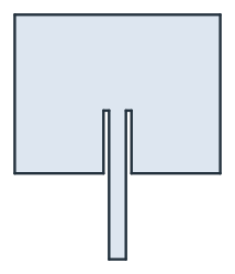
The copper is the patch minus two notches 1 wide beside the feed, plus the feed line from the edge of the board, 60 square (B), into the inset. Its end at the board edge is named port (Figure 1).
[4]:
B = 60.0
patch = px.QuickSketch().RectangleC(W, L).Face()
notches = [px.QuickSketch((x, -L / 2), dir=(1, 0)).Rectangle(1, y0).Face() for x in (-wf / 2 - 1, wf / 2)]
feed = px.QuickSketch((-wf / 2, -B / 2), dir=(1, 0)).Line(wf, name="port").Turn(90).Line(B / 2 - L / 2 + y0)
feed = feed.Turn(90).Line(wf).Close().Face()
copper = px.Subtract([patch, *notches]) + feed
copper.name = "patch"
Check: the copper’s area is the patch minus the notches plus the line outside the patch:
[6]:
exact = W * L - 2 * y0 + wf * (B - L) / 2
print("copper", copper.mass, "exact", exact)
copper 1097.5777343810907 exact 1097.5777343810907
On the board
The substrate is the 60 × 60 board extruded by 1.6, and its bottom is the ground plane. Gluing the copper onto its top splits the top face, so the mesh that netgen makes follows the patch.
[7]:
substrate = px.QuickSketch().RectangleC(B, B).Face().ToOCCFace().Extrude(h)
substrate.faces.Min(occ.Z).name = "ground"
board = occ.Glue([substrate, copper.Translated((0, 0, h)).ToOCCShape()])
board.faces.col = (0.20, 0.45, 0.25)
board.faces["patch"].col = (0.85, 0.55, 0.20)
board.faces["patch"].edges.hpref = 1
Draw(board)
Capacitance to ground
NGSolve solves for the potential with the copper at 1 V and the ground at 0 V, with the field in the substrate only. Check: under the patch, the field is close to the uniform field of a plate capacitor, and the field spreading at the edges adds about a tenth to its capacitance.
[8]:
mesh = ngs.Mesh(occ.OCCGeometry(board).GenerateMesh(maxh=3))
mesh.RefineHP(levels=2)
mesh.Curve(3)
fes = ngs.H1(mesh, order=2, dirichlet="patch|ground")
u, v = fes.TnT()
phi = ngs.GridFunction(fes)
phi.Set(1, definedon=mesh.Boundaries("patch"))
a = ngs.BilinearForm(ngs.grad(u) * ngs.grad(v) * ngs.dx).Assemble()
phi.vec.data += a.mat.Inverse(fes.FreeDofs()) * (-a.mat * phi.vec)

eps = 8.8541878128e-12 * er
C = eps * ngs.Integrate(ngs.grad(phi) * ngs.grad(phi), mesh) * 1e-3
print("C", round(C * 1e12, 3), "pF, plate capacitor", round(eps * copper.mass / h * 1e-3 * 1e12, 3), "pF")
Draw(phi, mesh)
C 29.982 pF, plate capacitor 26.725 pF