planex2d editor: parametric 2D CAD in the browser
The planex2d editor is parametric 2D CAD that runs in the browser. You draw a part in constraint sketches, with relations and dimensions that define its shape, and a tree of operations turns the sketches into the finished part with faces, Boolean operations, offsets, fillets and patterns. The part is saved as a DXF, SVG, STEP or BREP file, put on dimensioned technical drawings, or simulated in the editor. Everything is computed in the page, the geometry by the planex2d library and the simulations by netgen and NGSolve, so nothing is uploaded. Open the editor.
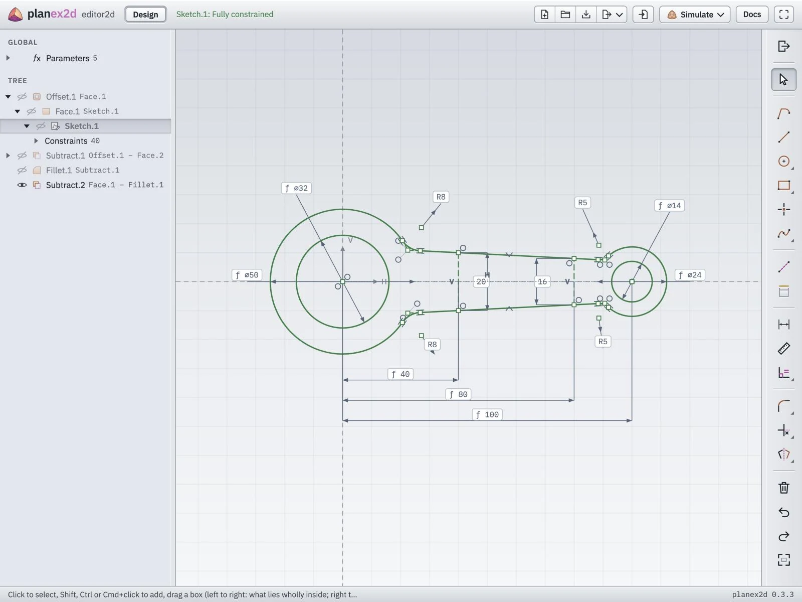
The sketch of a connecting rod, fully constrained.
This page follows one part through the editor, a connecting rod with a window in its shank, from its sketch to a stress result. Each section names the page that describes its tools.
A sketch that is solved
A sketch is drawn roughly and then defined by its constraints. Relations such as tangent, concentric or symmetric fix how the elements stand to each other, and dimensions fix their sizes. planex2d’s solver places the elements so that every constraint holds, and places them again when a value changes. Lengths are in millimeters and angles in degrees. The colors show the state of the sketch. A black element can still move, a green one is fully constrained, and red marks constraints that contradict each other.
The rod’s outline is two circles and two lines, trimmed where they cross and rounded with four fillets. Its dimensions are those of a drawing: the diameters of the eyes and the bores, the distance between their centers, and the width of the shank at two stations. With the last dimension, the sketch turns green and the header reads “Fully constrained”.
See Drawing in a sketch for the drawing tools and Constraints and dimensions for the relations, the dimensions and the colors.
Parameters and formulas
A parameter is a named number for the whole part, listed at the top of the tree. A dimension takes a formula of
parameters in place of a number. The diameter of the rod’s small eye is d + 2*rim, the bore and the rim around
it, and the two stations of the shank lie at 0.4*L and 0.8*L between the eyes. A dimension with a formula
shows an ƒ in front of its value. A changed parameter changes every dimension that uses it, and the tree computes
the part again.
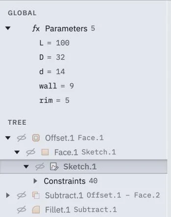
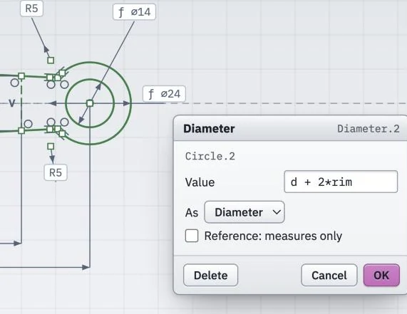
The part's parameters, and the diameter of the small eye given as a formula.
See Constraints and dimensions for parameters and formulas.
Curves
Besides lines, arcs and circles, a sketch holds splines and curves given by formulas. A spline runs through the points clicked, and each point can take a tangent angle, a tension and a radius of curvature. The default style is a quintic spline, and only this style takes a radius of curvature. Connect joins the ends of two elements with a curve that is tangent or curvature-continuous at both joins, and Curve draws a curve from two formulas, h(t) and v(t), over a range of t.
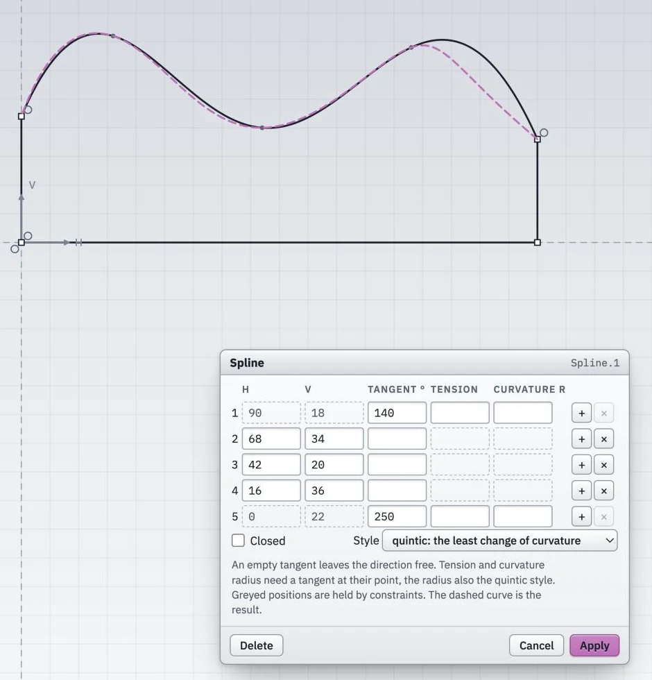
A spline's points, with a tangent angle typed at both ends. The dashed curve is the result.
See Drawing in a sketch for splines, B-splines and curves.
From sketches to a part
A part is a tree of operations. Each operation takes the results before it, and a change early in the tree computes everything after it again. The rod takes eight operations. Face turns the outline’s sketch into a face with the two bores as holes, and Offset shrinks that face by 3 mm. A second sketch and its face hold a disc around each eye, and Subtract takes the discs from the offset, which leaves the middle of the shank. Fillet rounds its corners, and a second Subtract cuts it out of the rod as a window.
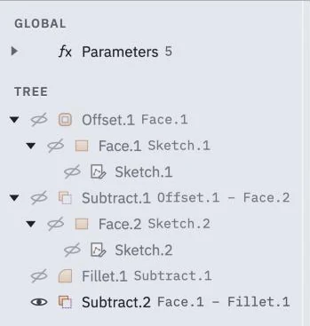
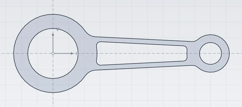
The eight operations of the rod, and their result.
See The Design tree for every operation.
Properties for meshing
Faces and edges of a result take a name, a color and mesh sizes. The rod’s face is named steel, and its two bores are named big end and small end, each with a largest element size. planex2d keeps these properties through the operations that follow, and the STEP file keeps the names and the mesh sizes.
The editor’s simulations build on them. A named edge or hole is a place for supports and loads, and the mesh follows the sizes set here. A script outside the editor does the same with the STEP file. It reads the file with planex2d, netgen meshes the part with these sizes, and the names become the regions and boundaries that materials, supports and loads refer to.
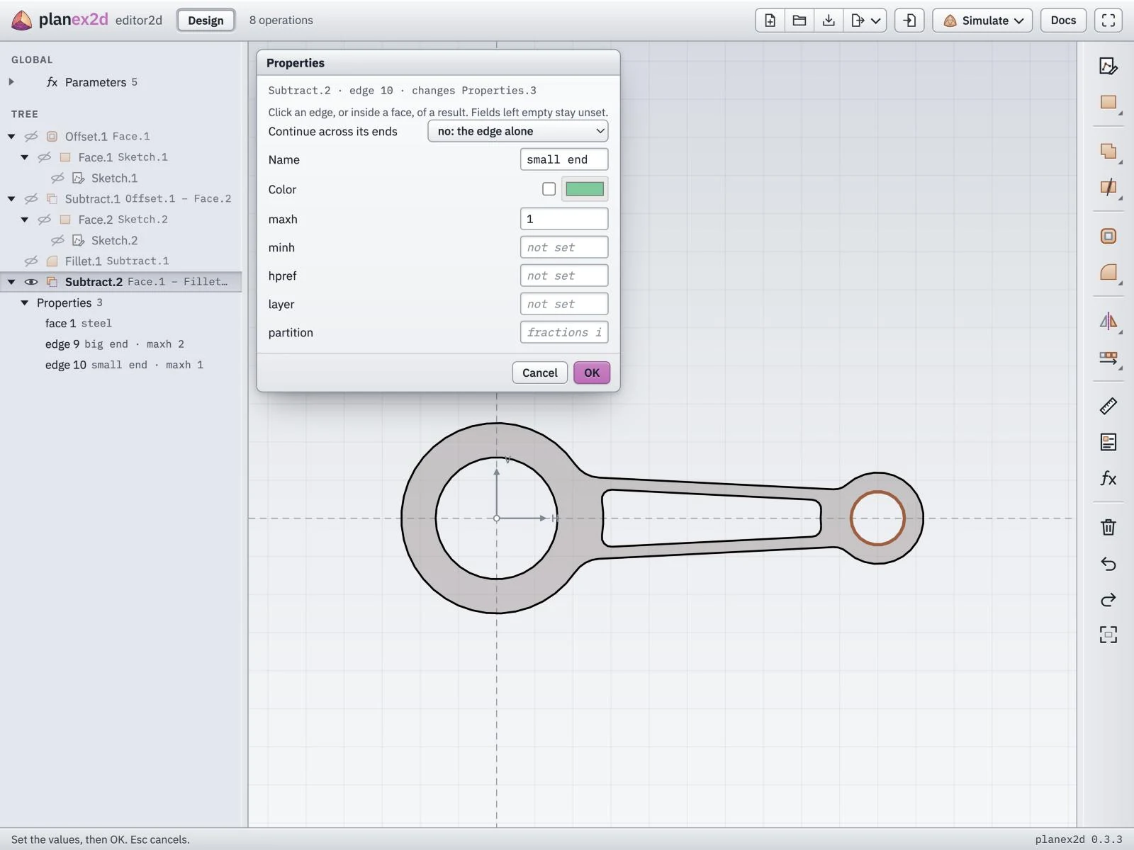
The small bore named small end, with the rod’s three properties listed in the tree.
See Properties for the fields, and Meshing a face in the planex2d docs for how names and mesh sizes reach a mesh.
Files
Save writes the part as a project file, which opens again with its sketches, dimensions and operations. Save as writes the result for other programs, as a DXF or SVG drawing or as a STEP or BREP model, and Import reads the same four formats into the tree. A DXF file keeps arcs and circles as arcs and circles, which laser cutters and CAM programs expect.
See Files for the formats and their options.
A drawing of the part
Drafting in the header switches to the drafting workbench, which makes technical drawings. Drafting on a new page puts the rod’s last operation on a page of its own, seen face-on, and Automatic dimensions dimensions it. On an A3 sheet at 2:1, planex2d gives the center distance, the bores, the radii of the eyes, the fillets and the taper of the shank. The title block takes the part’s name and number from the page settings, and Save as writes the page as PDF, DXF or SVG.
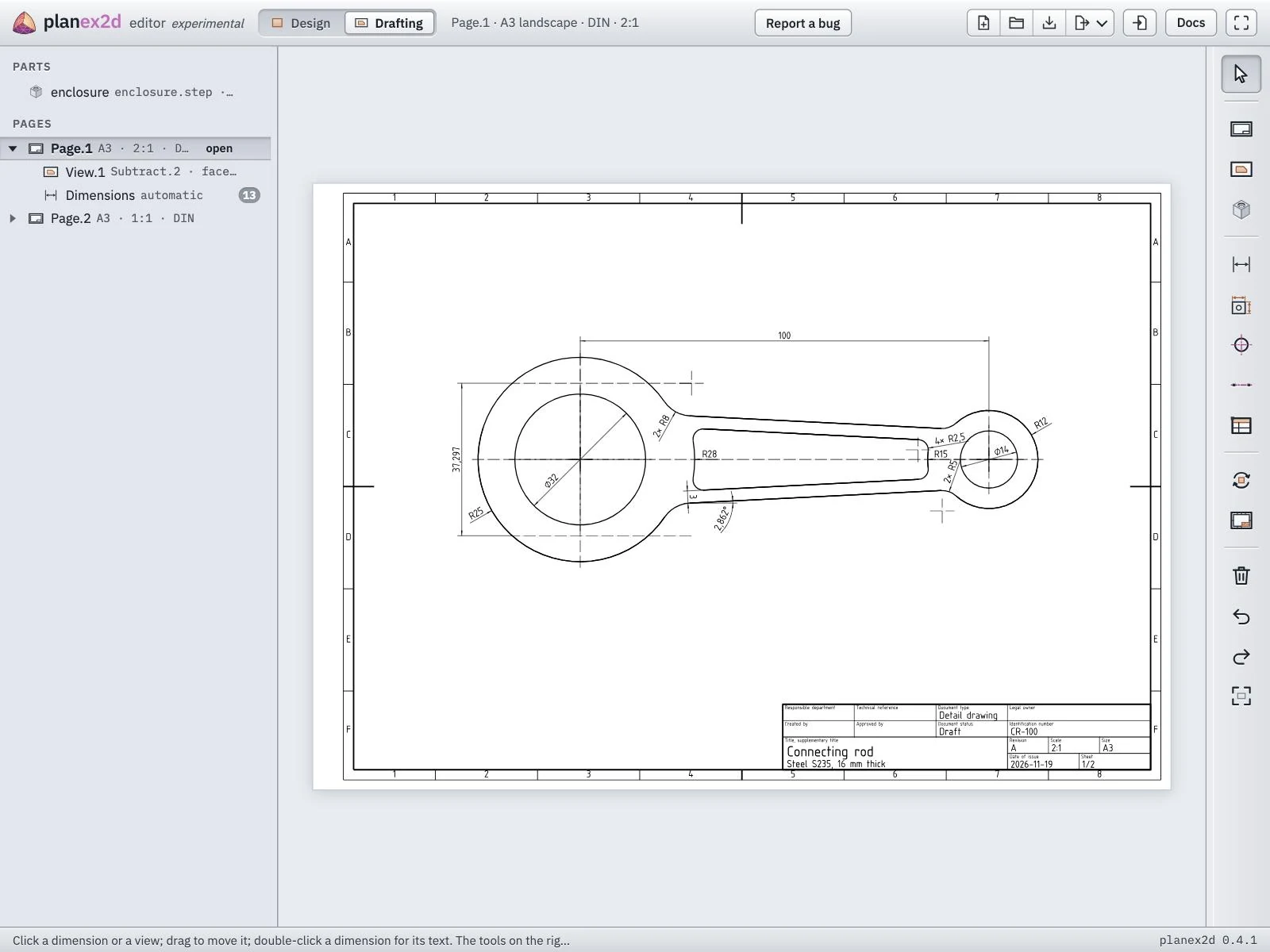
The rod on an A3 page, dimensioned automatically.
See Drafting for views of STEP parts, sections, dimensions placed by hand and the title block.
Into a simulation
The Simulate tools of the Design toolbar add a simulation of a result: a stress analysis, plate frequencies, heat transfer, electrostatics, magnetics or a beam. A simulation is an item below the tree, with a workbench for its material, its supports and loads and its results. Supports and loads go on the part’s edges and holes, by the names set with Properties.
In the stress analysis, the rod is 16 mm thick and made of steel S235. A bolt load of 5 kN pulls at each bore, as the two pins of the rod do, in opposite directions. The two loads balance, so balanced holding keeps the rod in place without a support. NGSolve solves the rod in plane stress, and the stress peaks at the small bore.
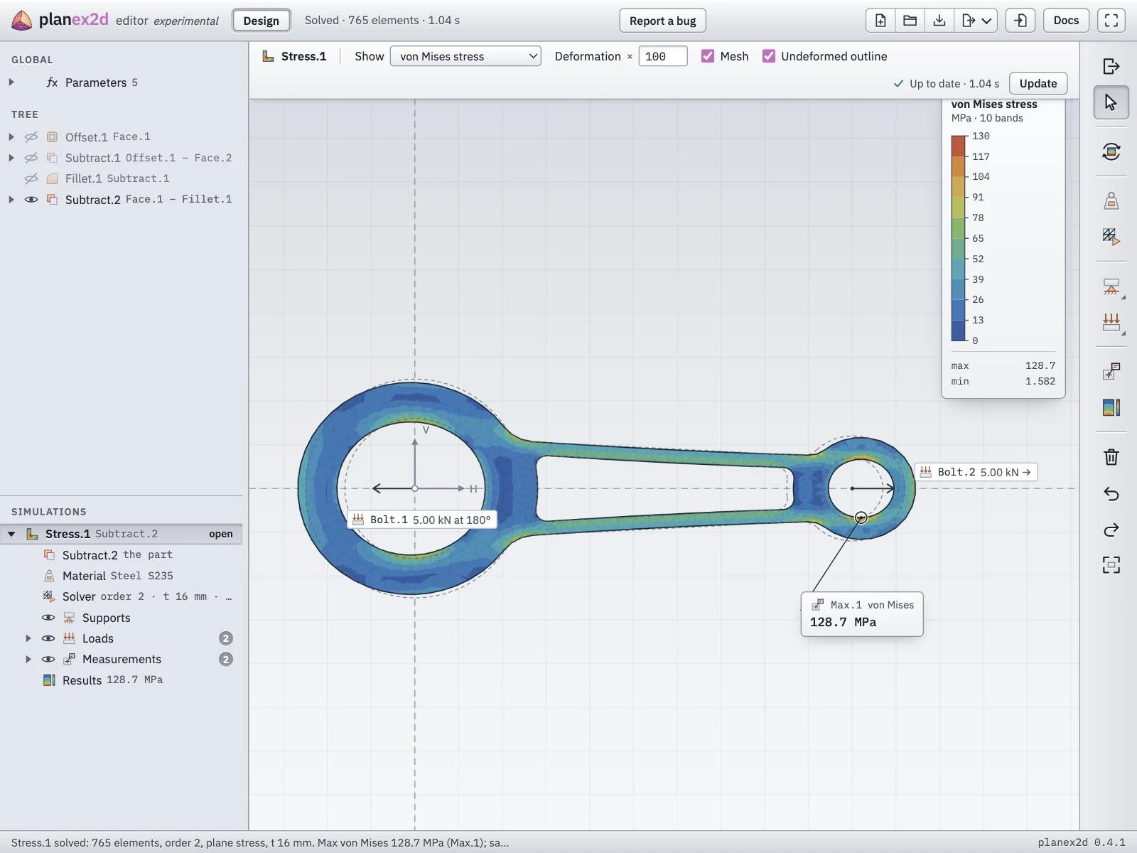
The rod in a stress analysis, pulled at both bores.
See Simulations for the six simulation types.
In your browser
The editor needs no account and no installation. planex2d runs in the page, so sketches, operations and files are computed on your computer, and the browser keeps a copy of the last part, which is back after a reload. The editor’s tools call the planex2d library, and the options of each tool are the options of its call. See the planex2d docs for the library and for the same steps in Python.
Where to go next
Page |
What it covers |
|---|---|
A first part, a plate with two holes, from the first line to a DXF file. |
|
The drawing tools of a sketch, snapping and selecting. |
|
Relations, dimensions, parameters and what the colors mean. |
|
Fillets, chamfers, trimming, offsets, mirrors and patterns in a sketch. |
|
The tree and its operations. |
|
Names, colors and mesh sizes of faces and edges. |
|
Lengths, areas, centers and second moments. |
|
Project files, importing, and saving drawings and models. |
|
Technical drawings: pages, views, sections, dimensions and the title block. |
|
The six simulation types, their workbenches and their results. |
|
Every tool with its icon. |
|
The keys. |