Drafting
Drafting makes technical drawings of the part. A drawing has pages, and a page holds views of Design results or of 3D parts read from STEP files, with their dimensions, center lines, tables and a title block. planex2d dimensions the views automatically, and each dimension can be moved, restyled or replaced by hand. The pages are written as PDF, DXF or SVG, and the project file keeps the drawing with the part. Drafting is still a work in progress, and its tools may change.
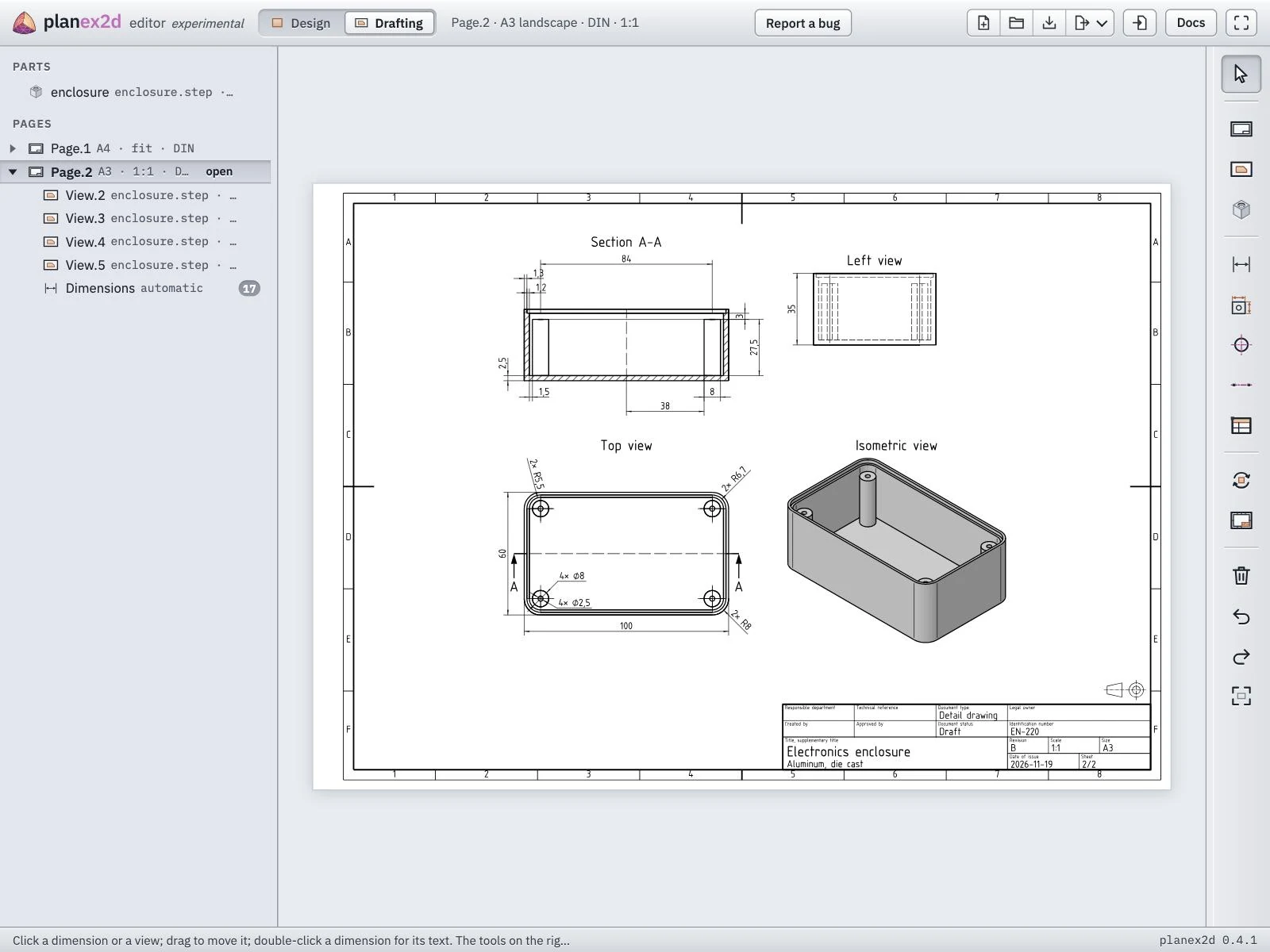
An enclosure from a STEP file on an A3 sheet, with a section, two views, an isometric view and the title block.
Opening Drafting
Drafting in the header switches to the drafting workbench, and Design switches back. In Drafting, the tree lists the drawing’s parts and pages, and the toolbar on the right holds the drafting tools.
Two tools of the Design toolbar take the selected result into a drawing. They share one button after the simulations, and the second opens beside it with a right-click, or a long press on a touch screen.
Drafting on a new page puts the result on a new page.
Drafting on the current page adds it to the page open in Drafting.
Drafting draws its views with OpenCASCADE. The editor loads it, about 10 MB, the first time Drafting opens in a session, and restarts the editor’s Python for it. The part, its parameters and its history stay as they are. A project that holds a drawing loads OpenCASCADE when it opens.
Pages and views
New page adds an empty page. A new page takes the settings of the page before it, until it is given settings of its own. A click on a page in the tree opens it.
Open STEP reads a 3D part from a STEP file into the drawing, where the tree lists it under Parts. It adds no view. New view puts a view of a Design result or of a STEP part on the open page.
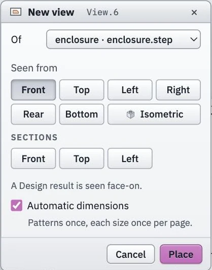
Click New view.
Under Of, choose a Design result or a STEP part.
For a STEP part, choose where it is Seen from: the front, top, left, right, rear or bottom, isometric, or one of the three sections.
Tick Automatic dimensions to have the view dimensioned, and click Place.
Click on the page where the view goes.
A front view of the enclosure, dimensioned automatically.
A Design result is seen face-on, the way it is drawn. The views of a STEP part line up with its front view in the page’s projection, so a top view goes below the front view in DIN and above it in ASME. A section cuts the part through the middle of its bounding box and shows the cut faces hatched. It takes a letter, A for the first, and the view of the same part that sees its plane edge-on marks the cut with that letter. Select drags a view to another place on the page.
A view of a Design result keeps the result as it was when the view was made. A later change of the result marks the view with ⟳, and Update takes the current geometry into every such view. A view whose operation is gone is marked with ×. A view of a sketch can take the sketch’s own dimensions, with the button from the sketch on its row in the tree.
View settings
A double-click on a view, on the page or in the tree, opens its settings. A field left empty shows in gray what the view gets without it.
Name replaces the name written above the view, such as Top view. A view of a Design result has no name until it is given one, and No name leaves out the name of a STEP part’s view.
A section keeps its letters after the name, so its cut stays marked on the view that sees its plane edge-on.
Hidden edges draws the hidden edges of a STEP part’s view, narrow and dashed. A section has none.
Automatic dimensions dimensions the view, as the tool of the same name does.
Scale draws an isometric view at a scale of its own, such as 1:2, written after its name. Left empty, the view is drawn at the page’s scale. The other views take the page’s scale for now.
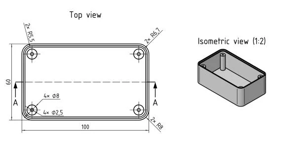
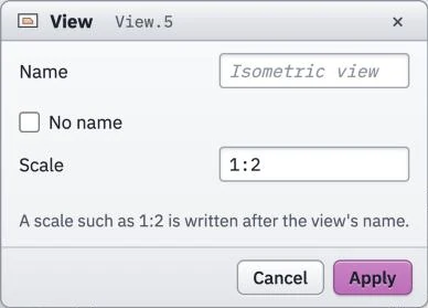
The enclosure's isometric view at 1:2, and its settings.
Dimensions
Automatic dimensions dimensions the selected views, or every view of the open page, as a drafter would. A pattern of holes is dimensioned once, with its count, and each size appears once on the page. Clicked again, the tool takes the automatic dimensions off. Delete hides a single automatic dimension, which stays hidden when the view is dimensioned again. An isometric view takes no dimensions.
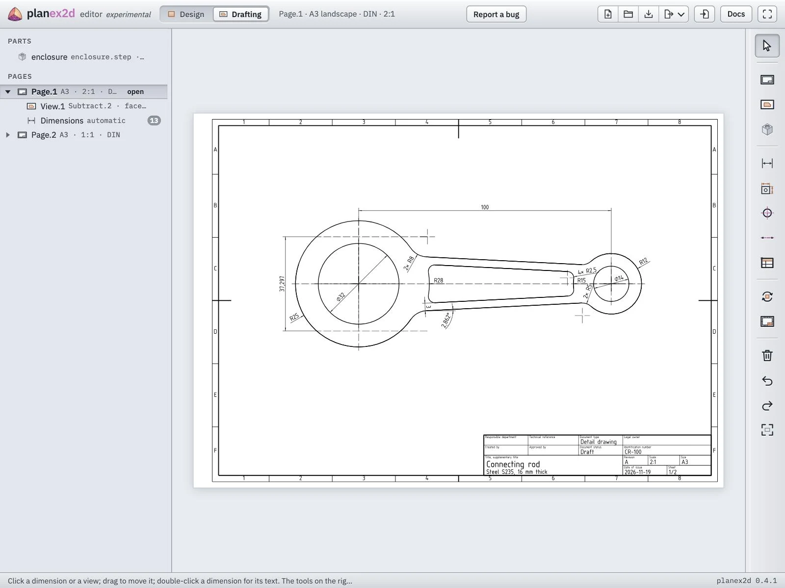
The connecting rod of the tour at 2:1, with its automatic dimensions.
Dimension adds a dimension by hand. Its kind follows from what is picked:
one line gives its length, a circle its diameter and an arc its radius;
two points give their distance, aligned, horizontal or vertical, depending on where the dimension is placed;
a point and a line give the distance of the point from the line;
two parallel lines give their distance, and two other lines the angle between them.
Click Dimension, then a line, a circle, an arc or a point of a view.
For a distance or an angle, click the second element.
Click where the dimension goes.
A dimension added by hand replaces an automatic one of the same size, so the size still appears once.
Moving a dimension
With Select, a click selects a dimension, a view or a table, and the selection shows in blue on the page and in the tree. A dimension is dragged on the page, and a preview of it follows the pointer until the page is drawn again.
A length moves its dimension line to the pointer.
A radius or a diameter turns around its circle. Dropped outside the circle, it goes on a leader, and dropped inside again, it comes off the leader.
An angle sets the radius of its arc.
A chamfer’s callout turns its leader.
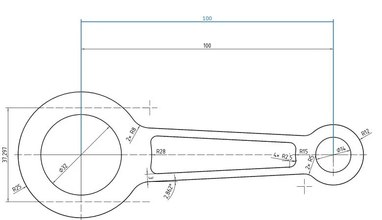
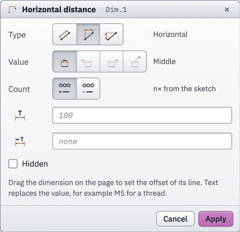
The rod's center distance dragged higher, and its popup.
The Dimension popup
A double-click on a dimension, on the page or in the tree, opens its popup. Each row is a group of buttons, of which one is pressed, with the name of the chosen option beside it. The popup shows only the rows that fit the dimension.
Type draws a length or a distance between two points at its true length, horizontally or vertically, and a circle by its radius or its diameter.
Value sets where a length’s value goes. The middle is the only choice yet, and a value moves beyond an arrow by itself where it does not fit between the extension lines.
Count writes the number of equal features before the value, such as 4×, from the patterns of the sketch, or no count.
Style draws a diameter as the layout chooses, through the center, on a leader, or across from outside, between two extension lines like a length. A radius has its arrow and value inside the arc, outside it, or on a leader.
Angle writes the angle as measured or its supplement, with the arc on the other side of a leg.
Below the rows, a text in the first field replaces the value, for example M5 for a thread. Left empty, the field shows the measured value in gray. R or ⌀ is added in front, except before a thread size. The second field adds a text after the value, for example EQS, and Hidden leaves the dimension out. Apply draws the page again. An automatic dimension keeps its type and its count, so its popup has no Type or Count.
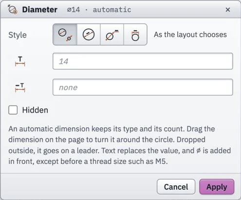
The rod’s small bore, an automatic diameter, with its four styles.
Center lines, axes and tables
Circles and arcs of a view get center lines as planex2d draws them. Center lines changes them for one circle or arc: a click on it opens a menu with lines across, a short cross, the horizontal arm, the vertical arm, or none. Axis draws a center line through two points, clicked one after the other, such as the axis of a turned part.
Table puts a table on a page that has a view, such as a parts list.
Click Table, then the page where its upper left corner goes.
Type the rows into the grid. The first row is the header, and Tab goes to the next cell.
Add rows and columns with Add a row and Add a column, and click Apply.
A double-click on a table opens its grid again, and Select drags it to another place.
Page settings and the title block
Page settings, or a double-click on a page in the tree, opens the settings of the open page.
Same as takes every setting from another page, so pages that belong together stay alike.
Sheet is A4 to A0. Orientation is upright for A4 and across for the larger sizes, unless landscape or portrait is chosen.
Standard is DIN, in first-angle projection with a decimal comma, or ASME, in third-angle projection with a decimal point.
Scale is a ratio such as 1:5 or 2:1. Left empty, it is the largest standard scale at which the page’s views fit, and the field shows that scale in gray.
Frame with zones draws the frame with its grid of zones.
The title block is planex2d’s own, after DIN EN ISO 7200, or one of your own from a DXF file, read with Open a DXF title block. A title block of your own has its fields as attribute definitions (ATTDEF) of the DXF file, and the settings list them under their prompts. Fill from a CSV reads the values from a CSV file, with a field’s name in the first column and its value in the second. Scale, size, date of issue and sheet fill themselves when left empty, the sheet as 1/2, 2/2 and so on, and their fields show these values in gray.
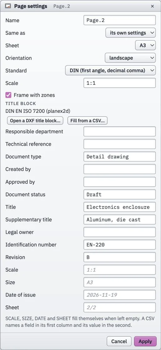
The settings of the enclosure’s page, with its title block filled in.
Writing the drawing
Save keeps the drawing in the project file with the part, the STEP parts included. Save as in Drafting writes the open page as PDF, DXF or SVG, at true scale. With two or more pages, PDF writes the open page or a zip with one PDF for each page.
See Files for project files, and Shortcuts for the keys of Drafting.