Constraints and dimensions
A sketch’s shape comes from its constraints, not from where its points were clicked. Relations such as parallel, tangent or equal fix how elements stand to each other, and dimensions fix lengths, distances, angles and radii. planex2d’s solver places the elements so that every constraint holds, and places them again whenever a value changes. This is what makes a sketch parametric, since a changed dimension changes the part. Lengths are in millimeters and angles in degrees.
The pictures on this page show the sketch of the connecting rod from the tour of the editor.
Relations
A relation is added to elements or points that are selected first.
Click Select, then the elements or points. Hold Shift, Ctrl or Cmd to add to the selection.
Right-click in the view, or click Constraints in the toolbar. The Constraints box lists the relations that fit the selection, and those that already hold are ticked.
Tick a relation to add it, or clear its tick to remove it.
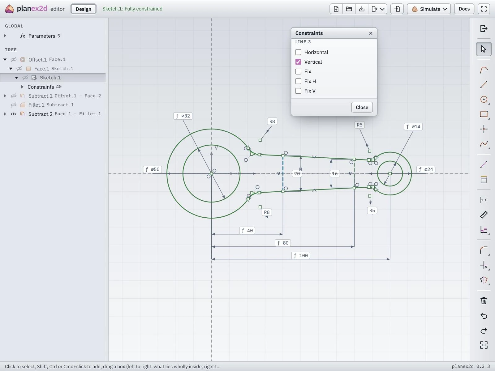
The relations offered for a station line of the shank, which is vertical.
Which relations the box offers depends on what is selected:
One line. Horizontal, Vertical, and Fix, Fix H or Fix V, which hold its position, its horizontal position or its vertical position.
One point. Fix, Fix H and Fix V. A circle or a spline offers Fix, and an arc Fix and Sweep angle, which adds its angle as a dimension.
Two lines. Coincident (collinear), Parallel, Perpendicular and Equal.
Two circles or arcs. Concentric, Equal and Tangent, and for two arcs Curvature (G2), the same curvature where they meet.
A line and a curve. A line and a circle can be tangent. Between lines, arcs and splines, Tangent and Curvature (G2) apply wherever an arc or a spline is one of the two.
A point and an element. A point and a line offer Coincident and Midpoint. A point and another point, a circle or an arc offer Coincident.
Three elements. Two points, or two elements of the same kind, and a line offer Symmetric, which mirrors the first two about the line. Three lines also offer Symmetric carriers, where the carriers of the first two lines mirror about the third and their lengths stay free.
Two more entries appear below the relations:
Symmetry line… makes two elements of the same kind mirror images of each other. After it, a click on a line, or on the H or V axis, sets the line of symmetry.
Rigid group makes two or more selected elements move as one body, keeping their shape and their distances.
Many relations come without asking. A shape such as a rectangle brings its own, and a point that snaps onto an element is tied to it.
Dimensions
A dimension fixes one size and shows it as a label in the view.
Click Dimension, then one or two elements or points.
Click where the dimension goes.
Type the value and press Enter.
What the picks give:
A line. Its length.
Two points, or a point and a line. Their distance, horizontal, vertical or aligned, depending on where the dimension is placed.
Two lines. Their distance if they are parallel, and their angle if they meet.
A circle or an arc. The diameter of a circle and the radius of an arc.
A circle or an arc with another element. The distance of its center from the point, the line or the other center.
A right-click after the picks offers the relations of the picked elements instead.
A double-click on a dimension, in the view or in the tree, opens its value again. The box offers what fits the dimension:
As switches a circle’s or an arc’s dimension between radius and diameter.
Reverse direction and Supplementary angle choose which of the angles between two lines is meant.
Swap side puts a distance on the other side of its line.
Reference: measures only turns the dimension into a measurement. It shows the value but holds nothing, so it never conflicts with the other constraints.
Delete removes the dimension.
Parameters and formulas
A parameter is a named number for the whole part, listed under Global > Parameters at the top of the tree. A dimension takes a formula of parameters in place of a number, and a changed parameter changes every dimension that uses it, in every sketch.
In the Design workbench, click Parameters in the toolbar.
Click Add parameter, type a name and a value, and click Apply. The rod has five, L = 100, D = 32, d = 14, wall = 9 and rim = 5.
Open the sketch, double-click a dimension and type a formula as its value, such as
d + 2*rimfor the diameter of the small eye or0.4*Lfor a station along the shank. Press Enter.
A dimension with a formula shows an ƒ in front of its value. The names h, v and t are reserved for the formulas of curves, so a parameter cannot take one of them.
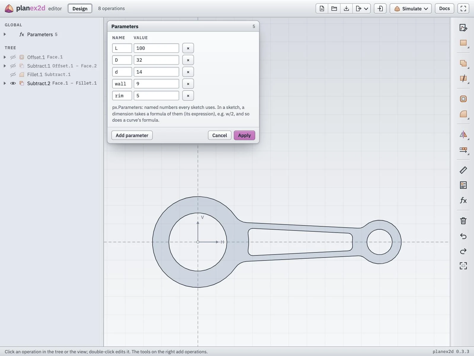
The Parameters table with the rod’s five parameters.
What the colors mean
Black. The element can still move. The header shows how many degrees of freedom the sketch has left.
Green. The element is fully constrained, and nothing about it can change.
Red. The sketch is over-constrained. A constraint contradicts the others, so the sketch has no solution with all of them. planex2d keeps the new constraint without solving it, its message in the status line names the constraints involved, and their rows in the tree turn red. Removing one of them, or changing its value, solves the sketch again.
Pink. A constraint is redundant. It repeats what the others already fix, the sketch still solves, and the header counts such constraints.
Gold. A projected reference, fixed by the result it was projected from.
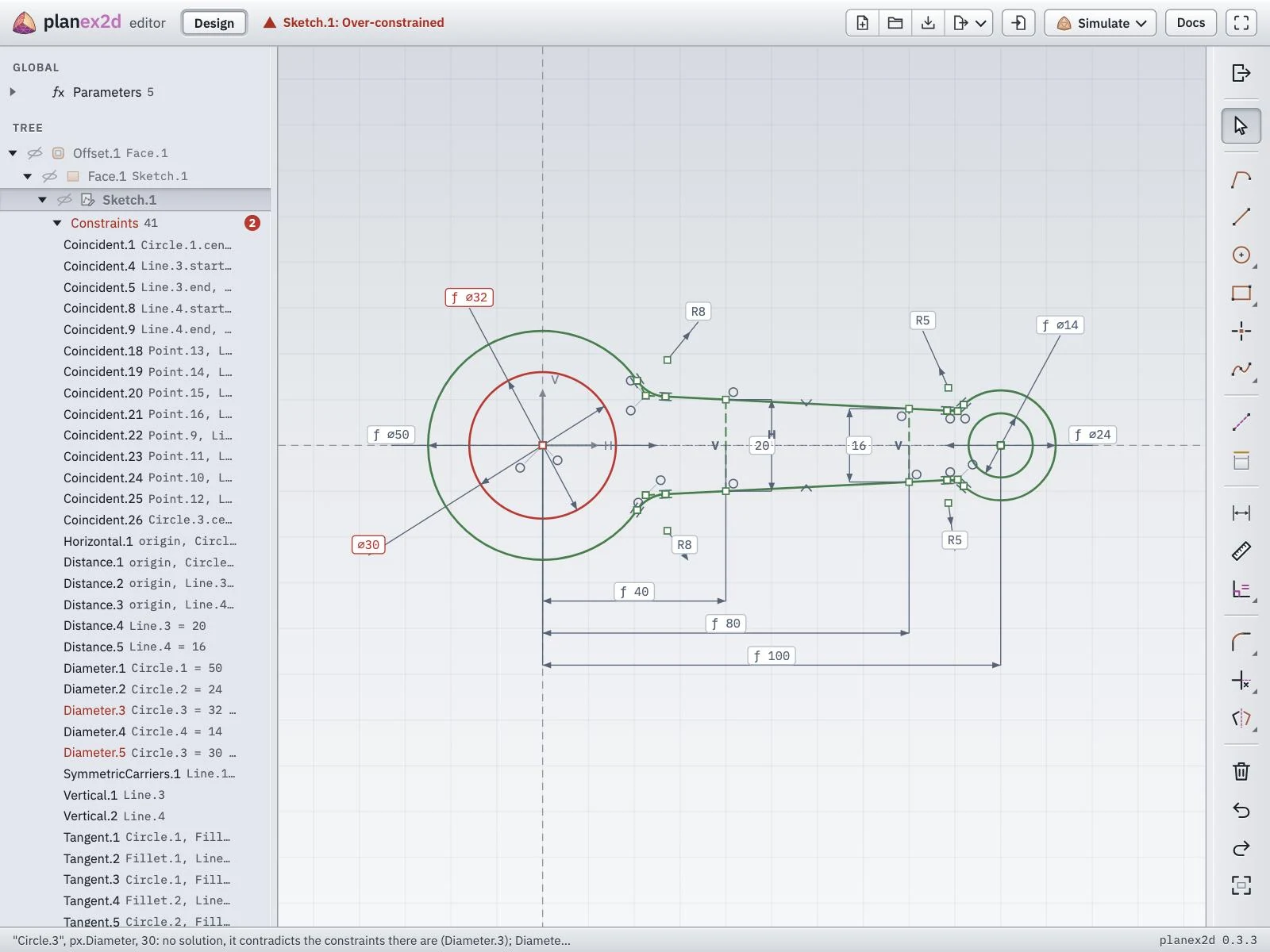
A second diameter on the big bore contradicts the first, and the sketch turns red.
The tree lists every relation and dimension of the open sketch in its Constraints folder. Hovering over a row highlights the elements it holds, a double-click edits its value, and × removes it.
See Constraint sketches and Fully, under- and over-constrained in the planex2d docs for the solver and its states.