Getting started
This page draws a first part, a plate of 80 × 50 mm with two holes of 12 mm. The plate is drawn as a constraint sketch, dimensioned until it is fully constrained, turned into a face and saved as a DXF file. Lengths in the editor are in millimeters.
The editor opens on the Design workbench. The tree on the left lists the part’s operations, the view in the middle shows their results, and the toolbar on the right holds the tools. The status line at the bottom says what the next click does. On the tool page the editor runs in a frame, and the icon at the right end of its header opens it on a page of its own.
Draw the sketch
The sketch is drawn roughly. Its exact sizes come from the dimensions in the next step.
Click New sketch at the top of the toolbar. The sketch opens in the view, and the toolbar shows the sketch’s tools.
Click Rectangle, then the origin, then the opposite corner of the plate. The rectangle keeps its right angles and its corner on the origin.
Click Circle, then the center of the first hole, then a point on its circle. Draw the second hole in the same way.
Where a click lands on another element, on an end or on one of the axes, the editor ties the new point to it.
Add the dimensions
Dimension takes one or two picks and then a click where the dimension goes. The value is typed and confirmed with Enter, and the solver moves the elements so that every dimension holds.
Click Dimension, then the bottom side, then a place below it. Type 80 and press Enter. Give the right side 50 in the same way.
Click one hole, then a place beside it, and type 12 for its diameter.
Go back to Select, select both holes and right-click. Choose Equal from the relations, so that the second hole takes the diameter of the first.
Click Dimension again. Pick a hole and the side next to it, and type 20. Pick the same hole and the bottom side, and type 25. Do the same for the other hole.
With the last dimension, nothing can move any more. Every element turns green, and the header reads “Fully constrained”.
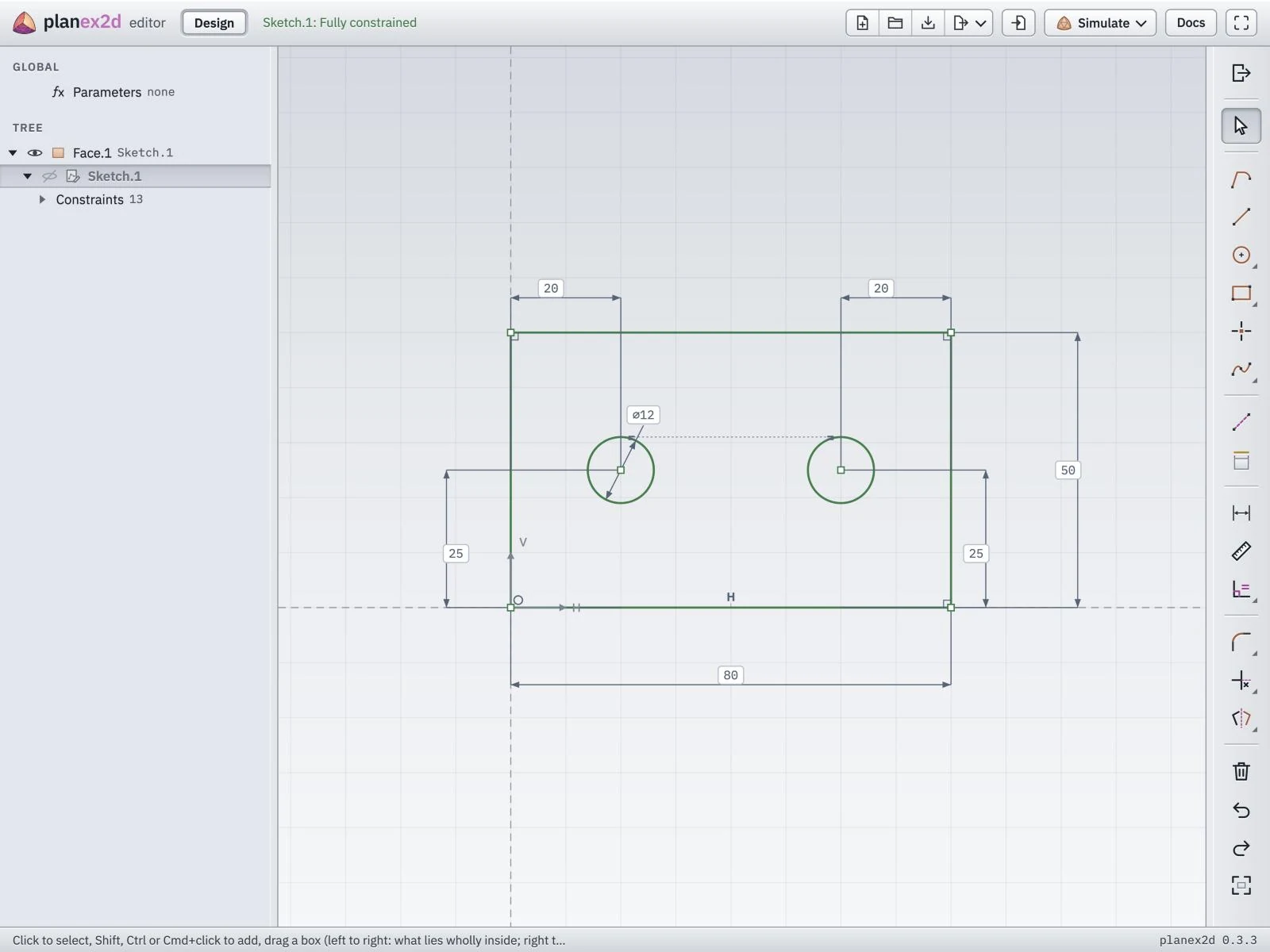
The plate’s sketch, fully constrained.
See Constraints and dimensions for the relations, the dimensions and what the colors mean.
Make the face
Click Exit at the top of the sketch’s toolbar. The sketch closes, and the toolbar shows the Design tools again.
Select the sketch in the tree and click Face. The closed outline becomes a face, with the two circles as holes.
The face appears in the tree with its sketch nested under it. A double-click on the sketch opens it again, and the face follows every change.
Save the part
Click Save as in the header and choose DXF. The file holds the outline in millimeters, as it was drawn, with the holes as circles.
Click Save to keep the part itself. The project file holds the sketch, its dimensions and the face, and Open reads it again.
The browser also keeps a copy of the last part on this computer, so the part is back after a reload.
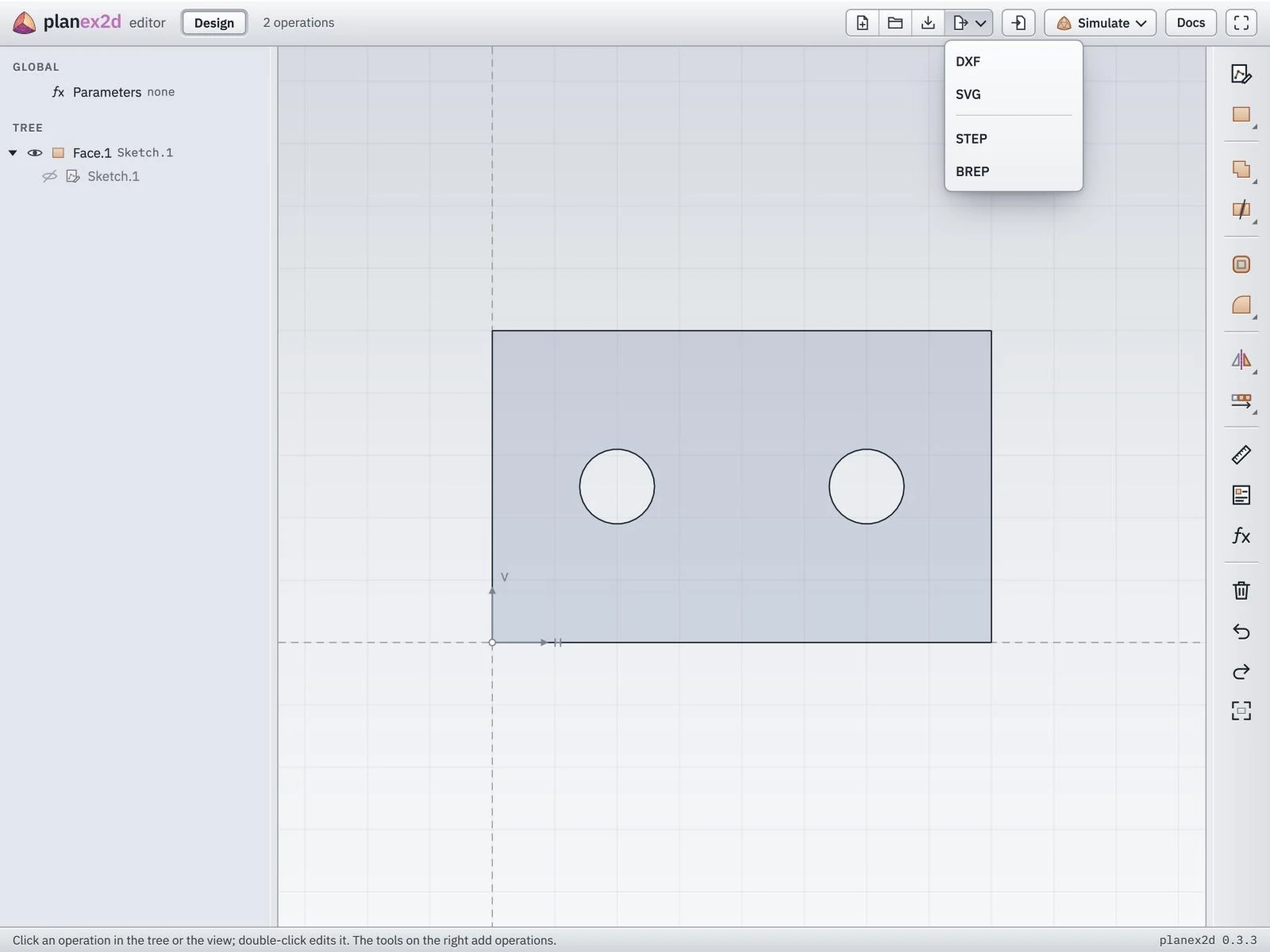
The plate as a face, with the Save as menu open.
See Files for the file formats and their options.
Next steps
A double-click on a dimension changes its value, and the face follows.
Parameters and formulas drive several dimensions with one number. See Constraints and dimensions.
Boolean operations, fillets and patterns shape the part further. See The Design tree.
Simulate opens the part in a stress analysis. See Simulations.