Tools / Electrostatics
2D electrostatics
Calculate the electric field and the capacitance of a cross-section or a rotationally symmetric part online and for free with the finite element method, from a DXF, SVG or STEP file. NGSolve solves the electrostatic field in this tab with Python, running on Pyodide/ngapp. Nothing is uploaded. If the drawing has gaps or doubled lines, clean it in the contour checker first.
Each region of the drawing gets its dielectric or is marked as metal, and the conductors take voltages or float with a given charge. The tool gives the potential and the field, the charge on every conductor, the capacitance, the stored energy and the highest field strength with its margin to breakdown, also around parts in open space. A PDF report and a CSV table hold the results.
- Planar and axisymmetric
- Runs in your browser
- Built on the planex2d library
Results
Open a part or one of the samples below, give each region its dielectric or mark it as metal, give the conductors their voltages by the numbers in the drawing and press Solve. After the first solve, a changed setting solves the part again. Regions and edges added under Measurements show their values in the results. Edges not in the table carry no charge and act as symmetry planes, and holes without a condition are filled with air. Lengths are in millimeters, voltages in volts, charges in nC and surface charges in µC/m². The PDF holds the field shown and the results on an A4 sheet, the CSV file the settings and the results. PDF (all) holds every field, and CSV (all) every field at the points of the drawing's grid.
Try a sample part
Each one opens in the electrostatics tool above with its materials and conductors. Download them to analyze the same parts with planex2d and NGSolve in Python.
-
Fig. 1DXF
Coaxial cable
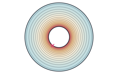
A coaxial cable with a 0.9 mm core in a polyethylene dielectric of 2.95 mm, at 1 kV between core and shield. Its capacitance is 105.44 pF per meter, the value of 2πε/ln(b/a), and the field is highest at the core with 1.87 kV/mm, a margin of 10.7 to the dielectric strength of the polyethylene.
-
Fig. 2DXF
Interdigital sensor
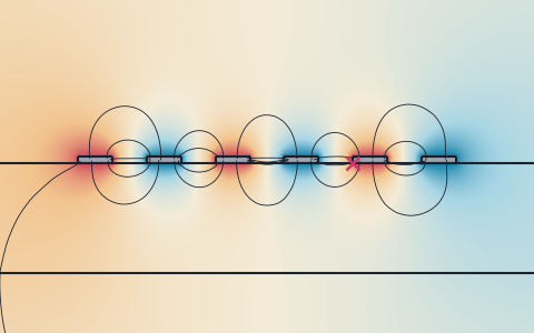
A capacitive sensor of six copper fingers on FR-4, 0.5 mm wide and 0.5 mm apart, connected in turn to 5 V and 0 V, in open space. Its capacitance is 1.43 pF over its length of 10 mm, and the field lines show how much of the field runs through the air above it, where a change of the surroundings changes the capacitance.
-
Fig. 3DXF
Spherical capacitor
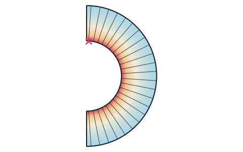
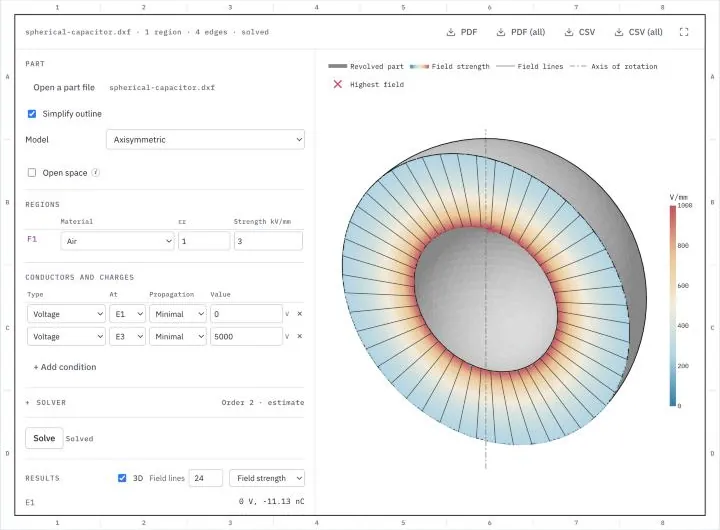
The classic spherical capacitor, a sphere of 20 mm diameter inside a grounded sphere of 40 mm with air between them, at 5 kV, solved as an axisymmetric part. Its capacitance is 2.2253 pF, the value of 4πε·ab/(b − a), and the field is highest at the inner sphere with 1.00 kV/mm, a margin of 3.0 to the 3 kV/mm of air.
-
Fig. 4DXF
Sphere above a plate
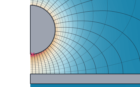
A sphere of 25 mm diameter 10 mm above a grounded plate at 15 kV, solved as an axisymmetric part in open space. The mean field across the gap is 1.5 kV/mm, but the field at the bottom of the sphere reaches 2.40 kV/mm, a margin of 1.25 to the 3 kV/mm of air. The capacitance is 1.90 pF.
What the electrostatics tool computes
The electric potential and field around conductors and in dielectrics, in the cross-section of a long part or in a rotationally symmetric part, with the charges and the capacitance that follow from them.
Conductors at different voltages set up an electric field in the insulation between them. How strong the field gets decides whether the insulation holds, and how much charge the conductors take up for a given voltage decides their capacitance. Formulas give both for a few shapes, such as a coaxial cable or a plate capacitor without its fringing field. For a real cross-section with several dielectrics, rounded and sharp edges and conductors in open space, they follow from a solution of the electrostatic field equation. The tool meshes the part and solves that equation with the finite element method, and shows the potential, the field and the place of the highest field strength.
Planar or axisymmetric
A planar model stands for a long part, such as a cable, a bus bar or a strip line, in which the field lies in the plane of the drawing. The Length gives the part's length, and the charges and the capacitance hold for that length and also per meter. An axisymmetric model stands for a part that is round about an axis, such as a bushing, an insulator or a sphere gap. The drawing is then the half-section right of its y axis, which is the axis of rotation, and the results hold for the whole part. With 3D on, the drawing shows the part revolved through half a turn, seen at an angle, with the field on its cut face on both sides of the axis.
Regions, dielectrics and metal
Every closed region of the drawing gets a number, F1, F2 and so on, and a material from the list, with its relative permittivity εr and its dielectric strength. A loop inside another on the same layer is a hole, and a loop on a layer of its own is an insert, a region of its own material. Regions that touch must lie on layers of their own. A region marked as metal is a conductor, which the field does not enter, and a hole without a condition is filled with air.
Edge, hole and interface numbers
The outline's edges get E1, E2 and so on from the lowest left corner around the part, every hole one number for its whole boundary, H1, H2 and so on from the left, and every edge between two regions I1, I2 and so on. The conditions refer to these numbers and to the metal regions' numbers, and the drawing shows them, with each edge's length on hover. The Propagation column carries a row on along the outline, with planex2d's selection propagation.
- Minimal keeps the edge alone.
- Coincident adds the edges joined to it end to end, which on a closed outline is all of it.
- Tangent adds the edges that continue it tangentially, such as the lines on either side of a fillet.
- Curvature adds the edges that continue its curvature as well.
Conductors and charges
- A voltage holds an edge, a hole or a metal region at a fixed potential, such as the core of a cable or a grounded shield at 0 V.
- A floating conductor is a metal part connected to nothing, with a given charge, usually 0. Its potential follows from the solution, such as that of a shield or a fitting that is not grounded. A metal region without a row floats with no charge.
- A surface charge puts a charge per area on an edge or an interface, such as a charged foil or an electret.
Conductors at the same voltage count as connected, so the capacitance of a comb of fingers at 5 V against one at 0 V is that of the two combs. Edges not in the table carry no charge, and the field lines run along them, as on a plane of symmetry.
Open space
With Open space on, the part sits in air that reaches to infinity, for parts such as a two-wire line or a sphere above a plate that no grounded enclosure surrounds. The tool adds an air region around the drawing, and around that a thin layer whose coordinates a map stretches out to infinity. The solution in the layer is then that of all the space outside, and the result does not depend on the size of a box, as it would with a box held at 0 V. In a planar model no charge leaves the part to infinity, and in an axisymmetric model infinity is at 0 V, so a single sphere has its capacitance to infinity.
Measurements
The Measurements group, folded below the conductors, adds values for the regions and edges you choose to the results.
- A dielectric region gives its mean and highest field strength, its breakdown margin and the energy stored in it, and a metal region its voltage and charge.
- An edge, a hole or an interface, carried on with the Propagation column, gives its length, its mean potential, the voltage ∫E·dl along it and the flux of the displacement D across it. On the edges of a conductor this flux is the conductor's charge, and along an equipotential ∫E·dl is 0.
Results
The results are the voltage and the charge of every conductor, the capacitance between the conductors at the two voltages, the energy stored in the field and the highest field strength with its place. For three or more conductors the tool also gives the capacitance matrix. For each material it gives the highest field in it and the breakdown margin, its dielectric strength divided by that field. The drawing colors the field by the potential with its equipotential lines, or by the field strength, its components, the displacement or the energy density with the list beside Results. Field lines along the field can be added, as many as the number beside Results. They start on the conductors in proportion to their charge, so they crowd where the field is strong.
At a sharp metal corner the field of an electrostatic solution grows without limit, so the highest field there depends on the mesh. The accuracy estimate in the Solver group shows this as a large change. A conductor drawn with its real radius gives the field at that radius.
Simplify outline
Drawings often carry arcs and holes as chains of short lines, which give the outline many edge numbers. With Simplify outline on, planex2d fits arcs to such chains, within a ten-thousandth of the part's size, before the part is numbered and meshed. Turn it off to analyze the outline exactly as drawn. Where the fit misses an arc, the contour checker fits arcs with a tolerance and an edge length of your choice, closes gaps and removes tiny edges, and saves the cleaned drawing for the electrostatics tool.
Units
Lengths are in millimeters, voltages in volts, field strengths in V/mm, dielectric strengths in kV/mm, charges in nC and surface charges in µC/m², the displacement in µC/m² and the energy density in J/m³. A file is read in the unit it names and converted to millimeters.
How the electrostatics tool works
The tool is a small page around the planex2d Python library, with NGSolve for the finite element solution. It runs the same code you get with pip install "planex2d[occ]" ngsolve, compiled to WebAssembly and loaded with Pyodide/ngapp.
- Load
The page loads Python and planex2d into this tab, and NGSolve with the first solve, about 23 MB the first time. Your browser keeps them in its cache, so later visits start faster.
- Read
planex2d reads the file, joins its closed contours into regions, simplifies the outline and numbers its regions, edges and holes.
- Solve
NGSolve meshes the part and solves the electrostatic field equation, again whenever a setting changes after the first solve.
- Save
The results are saved as a PDF report or a CSV table, made in the tab as well.
The finite element model
The mesh has elements of about a thirtieth of the part's size, finer along arcs, short edges and conductors, and it is curved to the exact outline. The hp refinement in the Solver group refines the mesh geometrically toward every vertex and edge of the part, as many levels deep as given, since the field changes fastest there, and it integrates the refined elements with a higher order. It is off by default, and 3 levels sharpen the field at sharp corners. NGSolve solves the field equation with second-order elements, set from 1 to 5 in the Solver group, and a sparse Cholesky factorization. The tool solves once for every conductor at 1 V with the others at 0 V, which gives the capacitance matrix, and combines these solutions to the voltages given. Floating conductors then take the voltages at which their charges come out as given, without an approximation.
How it is tested
The tests solve parts whose capacitance, field or potential is known exactly and compare the tool's values with those, with second-order elements and third-order elements for the cases in open space. A plate capacitor has a uniform field, which the elements represent exactly, so its cases agree to the last digit. The curved cases agree within the error of the mesh.
| Case | Exact value | The tool | Difference |
|---|---|---|---|
| Coaxial line, core 2 mm, shield 7 mm, εr 2.25: capacitance | 2πε/ln(b/a) = 99.91765 pF/m | 99.91775 pF/m | 1.0 × 10⁻⁶ |
| The same line: field at the core, 1 V | V/(a ln(b/a)) = 0.79824 V/mm | 0.79817 V/mm | 8.8 × 10⁻⁵ |
| Floating metal sheet in a plate capacitor, gaps 4 and 5 mm: its voltage | 4/9 V = 0.444444 V | 0.444444 V | 2.5 × 10⁻¹⁶ |
| The same capacitor: capacitance | ε W/(d₁ + d₂) = 39.35195 pF/m | 39.35195 pF/m | below 10⁻¹⁵ |
| Charged interface between two grounded plates, 1 µC/m² | σ d/(2ε) = 282.35 V | 282.35 V | 1.8 × 10⁻¹⁵ |
| Spherical capacitor, spheres of 20 and 40 mm, axisymmetric: capacitance | 4πε·ab/(b − a) = 2.225300 pF | 2.225307 pF | 3.1 × 10⁻⁶ |
| The same capacitor at 1 V: field at the inner sphere | V b/(a (b − a)) = 0.2 V/mm | 0.20048 V/mm | 2.4 × 10⁻³ |
| Two-wire line in open space, d/2a = 2: capacitance | πε/acosh(d/2a) = 21.12160 pF/m | 21.12160 pF/m | 1.2 × 10⁻⁷ |
| Sphere of radius 1 mm in open space, axisymmetric: capacitance | 4πεa = 0.111265 pF | 0.111265 pF | 2.7 × 10⁻⁸ |
| The same sphere at 1 V: field at its surface | V/a = 1 V/mm | 1.0002 V/mm | 1.7 × 10⁻⁴ |
Supported files
| Format | Extensions | Notes |
|---|---|---|
| DXF | .dxf | The part's lines, arcs, circles, polylines, splines and ellipses, on every layer. A closed loop on a layer of its own is an insert. See Files. |
| SVG | .svg | Paths and shapes. See SVG. |
| STEP | .step .stp | Planar parts. See STEP and BREP. |
| BREP | .brep | Planar parts, taken in meters, since BREP names no unit. |
.pdf | The report with the field shown, the settings and the results on an A4 sheet. PDF (all) has every field. | |
| CSV | .csv | The settings and the results, with the capacitance matrix. CSV (all) is one table with a row for every point of the drawing's grid in the field and every field there. |
Run it in Python
The same analysis takes a few lines with planex2d and NGSolve. The example is the coaxial cable sample, a core of 0.9 mm in a polyethylene dielectric of 2.95 mm with εr = 2.25. planex2d draws the section and names its two circles, and NGSolve meshes it and solves for the potential with the core at 1 V and the shield at 0 V. The field energy then gives the capacitance per meter, C = ε∫|∇V|² for 1 V. See Meshing with netgen in the docs, and the microstrip impedance example for a field solve in a trace's cross-section.
$ pip install "planex2d[occ]" ngsolveimport math
import ngsolve as ngs
import planex as px
coax = px.QuickSketch().Circle(1.475).Circle(0.45).Face()
for e in coax.edges:
e.name = "core" if e.mass < 3 else "shield"
mesh = ngs.Mesh(px.OCCGeometry(coax).GenerateMesh(maxh=0.1))
mesh.Curve(2)
fes = ngs.H1(mesh, order=2, dirichlet="core|shield")
u, v = fes.TnT()
a = ngs.BilinearForm(2.25 * ngs.grad(u) * ngs.grad(v) * ngs.dx).Assemble()
gf = ngs.GridFunction(fes)
gf.Set(1, definedon=mesh.Boundaries("core"))
r = -a.mat * gf.vec
gf.vec.data += a.mat.Inverse(fes.FreeDofs(), inverse="sparsecholesky") * r
c = ngs.Integrate(2.25 * ngs.grad(gf) * ngs.grad(gf), mesh) * 8.8541878128
print("C", round(c, 3), "pF/m, exact", round(2 * math.pi * 2.25 * 8.8541878128 / math.log(1.475 / 0.45), 3))It prints a capacitance of 105.439 pF per meter, against 105.439 pF from 2πε/ln(b/a).
Privacy
Nothing is uploaded. The file is read, meshed and solved in this tab and is gone when you close it. Python, planex2d and its packages come from public package servers (jsDelivr and PyPI), and NGSolve from this site. See the privacy notice.
Limits
- The tool solves the electrostatic field with constant, isotropic permittivities. Currents, magnetic fields, losses and frequency effects are not computed.
- A planar model assumes no field along the part, and an axisymmetric model a part and a field that are round about the y axis.
- The dielectric strengths are typical values, and the breakdown margin compares them with the field. It is not a prediction of the breakdown voltage, which also depends on the gap, the thickness, the voltage form and the surface.
- The field at a sharp metal corner depends on the mesh. Draw conductors with their radii where the highest field matters.
- A volume charge in a dielectric is not part of the tool, and a file must be planar, and its text, dimensions and hatches are not read.
- A part that fails or a result that looks wrong? Open an issue on GitHub and attach the file if you can.
Questions and answers
Is my file uploaded?
No. planex2d reads the file in this browser tab, running on Pyodide/ngapp, and NGSolve solves the field there as well. The file is gone when you close the tab. Python and its packages come from jsDelivr and PyPI, NGSolve from this site, and your file is never sent anywhere.
How do I calculate the capacitance of a cable or a capacitor?
Open its cross-section, give the insulation its material and mark the conductors as metal regions, or leave them as holes. Then give one conductor a voltage, the other 0 V, and enter the length for a planar part. The results give the capacitance between the two, per meter and for that length. The coaxial cable sample does this and matches 2πε/ln(b/a) to five digits.
What does Open space do?
It puts the part in air that reaches to infinity, for a part that is not inside a grounded enclosure, such as a two-wire line or a sphere above a plate. The tool adds an air region around the drawing and a layer around it that a coordinate map stretches out to infinity, which is exact rather than a box of finite size. Without it, the drawing's outer edges bound the field.
What is the breakdown margin?
It is the dielectric strength of a material divided by the highest field in it, so a margin below 1 means the field exceeds the strength. The strengths in the material list are typical values, about 3 kV/mm for air. Real breakdown also depends on the gap, the thickness, the voltage form and the surface, so the margin is a check of the design, not a prediction of the breakdown voltage.
Is this a real finite element analysis?
Yes. NGSolve solves the electrostatic field equation with second-order elements on a mesh of the exact outline, with several dielectrics, conductors at a voltage, floating conductors and surface charges, planar or axisymmetric. The tests compare it with the exact capacitances of a coaxial line, a spherical capacitor, a two-wire line and a sphere, and with a floating sheet in a plate capacitor.
Why does the highest field change when I refine the mesh?
At a sharp metal corner the field of an ideal electrostatic solution grows without limit, so its value at the corner depends on the mesh, and the accuracy estimate shows a large change there. A real conductor has a radius at that corner. Draw it with its radius to get the field that it sees, or read the field a short distance away from the corner.
Other tools on planex2d.org
Every tool runs on the planex2d library, in your browser.
-
Magnetics
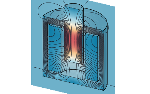
Magnetic fields, inductances and forces of cross-sections and round parts from DXF, SVG or STEP files, with B-H curves, permanent magnets, coils in circuits, eddy currents and the skin effect.
-
PCB impedance
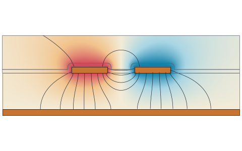
Characteristic and differential impedance of microstrip, stripline and coplanar traces from the board stackup or a KiCad board, with losses and the width for a target impedance.
-
Heat transfer
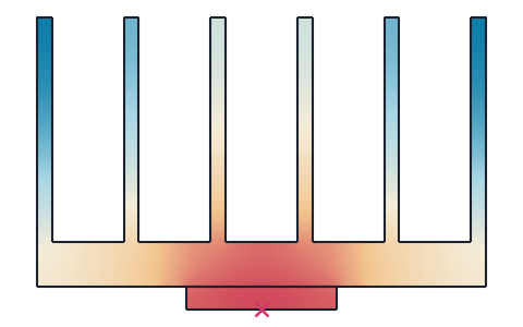
Steady and transient 2D heat transfer of profiles, heat sinks and plates from DXF, SVG or STEP files, with several materials, convection, radiation and contact resistances, and the thermal resistance.
-
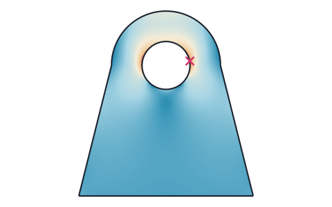
Stress analysis
Finite element stress analysis of flat parts from DXF, SVG or STEP files, with supports and loads by edge and hole number, the von Mises and principal stresses, the deformed shape and a safety factor.
-
Playground
planex2d code in the browser, with OpenCASCADE for 3D solids and netgen and NGSolve for finite elements, shared as a link that carries the code.
The planex2d Online Tools page lists every tool, and the planex2d documentation shows the library behind them.