Tools / STEP to drawingExperimental
STEP to drawing
Make a dimensioned 2D drawing of a 3D part online and for free from its STEP file: the standard views, an isometric view and sections, dimensioned automatically, with a title block, as a PDF, SVG or DXF file. planex2d draws the views with OpenCASCADE in this tab, running on Pyodide/ngapp. Nothing is uploaded. AI agents can also use it through WebMCP. For more demanding work, the Drafting workbench of the planex2d editor draws the same views and lets you place, move and restyle every dimension by hand, on drawings of several pages.
The Views table lists the views of the sheet, which take their places in first-angle projection after DIN practice or in third-angle projection after ASME practice. A title block of your own can come in as a DXF file, and its fields are filled in by hand or from a CSV file. The dimensions come from planex2d's automatic dimensioning, which looks for symmetry, hole patterns and the part's datum as a drafter would.
This tool brings planex2d's dimensioned drawings to the browser. Their automatic dimensions are currently being worked on, so the tool is experimental. A STEP file holds the part's faces and edges but not the sketches it was modeled with, so the dimensions have to be found again across the views, with the part's patterns and symmetries. Many prismatic and turned parts already come out as a good first draft, while more complex parts such as gears might not come out perfect yet. Check every drawing before you use it.
- DIN and ASME practice
- Runs in your browser
- Built on the planex2d library
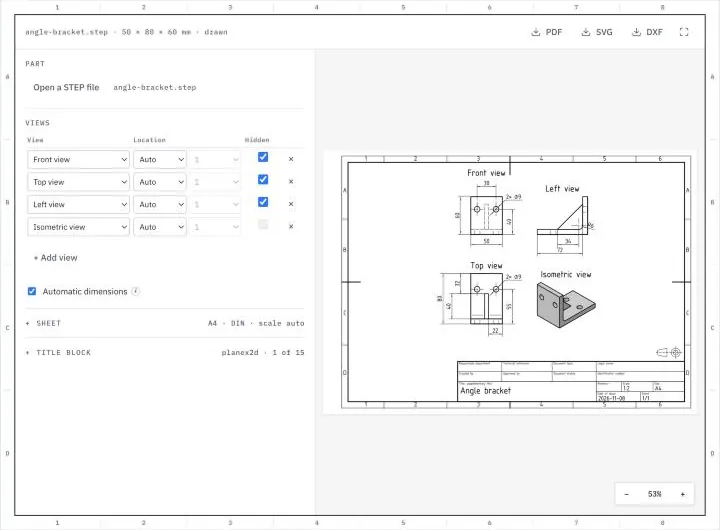
Open a STEP file or one of the samples below, list the views in the Views table and set the sheet and its title block. The sheet is drawn again after every change. Each view takes its place in the standard's projection, or in the grid zone its Location names, and the largest standard scale at which every view fits is chosen unless you set one. The buttons at the preview's lower right, Ctrl and the mouse wheel, or a pinch zoom into the sheet. The PDF and the SVG file hold the sheet at true scale, and the DXF file holds the views at true size in millimeters with real dimension entities, to plot at the sheet's scale.
Try a sample part
Each one is a part of the CAD practice drawings in the planex2d documentation, as the STEP file its page writes, and opens in the drawing tool above with its views and sheet.
-
Fig. 1STEP
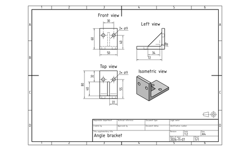
Angle bracket
The angle bracket of the practice drawings, 50 × 80 × 60 mm with a rib and two holes of 9 mm in each leg, as front, top and left views and an isometric view on an A4 sheet in DIN practice. The tool picks the scale 1:2 and gives each pair of holes as 2× ⌀9 in the view where they are round.
-
Fig. 2STEP
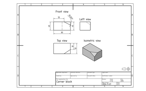
Corner block
A block of 80 × 50 × 40 mm with one corner cut off at a slant, on A4 in DIN practice at 1:2. The front view gives the cut by its angle of 26.565°, where a drafter might give the depth of the cut instead, so it is a dimension to check.
-
Fig. 3STEP
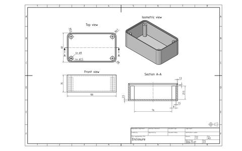
Enclosure
A small enclosure of 100 × 60 × 35 mm with rounded corners and four screw bosses, on A3 in ASME practice at 1:1: the top view above the front view in third-angle projection, a section A-A through the middle and an isometric view. The bosses come out as 4× ⌀8 and 4× ⌀2.5.
What the drawing tool draws
A technical drawing of a solid part from its STEP file: views, sections and an isometric view on a sheet with a frame and a title block, dimensioned automatically.
A STEP file holds a part as a 3D solid, the way a CAD program exports it, but a workshop, a quote or an inspection often still needs a 2D drawing of it. A drawing shows the part in views along its main directions, with the hidden edges dashed, sections where the inside matters, and the dimensions that define its shape. The tool draws these views from the solid with OpenCASCADE's exact hidden-line removal, so every circle and arc of the part stays a true circle or arc on the sheet, and dimensions them with planex2d.
Views and sections
The Views table holds one row per view:
- The front, top, left, right, rear and bottom views show the part along the coordinate axes of its STEP file. The front view looks along the y axis and the top view down the z axis. The Hidden column draws their hidden edges dashed.
- The isometric view shows the part shaded, in isometric projection.
- A section cuts the part through its middle, parallel to the front, top or left view, and shows the cut faces hatched. Its cutting line, with the section's letters, is drawn on a view that sees the plane edge-on.
The Location column places each view. Auto puts a standard view where the projection puts it, beside the front view and aligned with it. The isometric view goes into the free corner diagonal to the front view, between the side view and the top view, and the sections go beside the other views. A grid zone of the frame, such as B5, with its row's letter from the top and its column's number from the left, puts the view's middle, its dimensions included, at the middle of that zone instead, out of the projection's line-up. The row and the column lists also hold the half steps between two neighbors, such as B–C or 5–6, which put the view's middle on the line between two fields or on the corner where four meet.
The scale is the largest at which every view fits. A view placed so close to the frame or the title block that it runs over them at every scale is left out of that choice and drawn where its zone puts it. A note below the panel says when this happens, and when two views overlap or one runs over the frame or the title block.
Automatic dimensions
A STEP file holds the part's faces and edges, not the sketches and the design intent it was built from, so the tool finds that intent again from the geometry. For each view it turns the visible edges into a sketch of their own and lets planex2d's auto constraints find what a drafter would see: concentric circles and tangent edges, symmetry about an axis, equal holes in a row or on a bolt circle, and the datum the sizes are measured from. The dimensions then follow in a drafter's order, with angles, diameters and radii first, then the distances, horizontal and vertical ones and round values first. A chamfer at 45° gets one callout, its leg times 45°, such as 0,4 × 45°. On the sheet each size appears once, in the first view that shows it, and a diameter in the view where its circle is round. Edges that are neither lines nor arcs, such as the ellipse of a hole seen at a slant or a helix, get no dimensions.
This works well for parts made of prismatic and cylindrical features, but it remains a guess at the design intent. It can miss a size a drafter would show, measure a feature from another edge than the one that matters for its function, or read a pattern into features that only look alike. Treat the result as a first draft and check it against the part. The DXF file can be corrected in a CAD program.
The sheet and its scale
The sheet is A4 to A0, upright or on its side, with a frame, grid reference zones and the title block in its lower right corner. Auto lays A4 upright and the larger sizes on their side. The scale is the largest of the standard scales, 1:1, 1:2, 1:5, 2:1 and so on, at which the views and their dimensions fit the drawing area, unless the Scale list sets one.
The title block
Without a title block of your own, the sheet carries planex2d's, with fields for the department, the author, the title, the drawing number, the revision and the rest of a drawing's data. Open a title block (DXF) takes your own, a DXF file whose fields are attribute definitions (ATTDEF), as in the title blocks of AutoCAD and BricsCAD. The Title block table lists the fields it finds with their prompts, and what you type fills them in. The scale, the sheet size, the date and the sheet number fill themselves where the block has these fields, unless you type them.
Open field values (CSV) fills the fields from a CSV file with two columns. Each row holds a field's placeholder, the tag of its attribute definition such as TITLE or NUMBER, or the field's name as the table lists it, and then the value. Commas, semicolons and tabs all work as separators, a first row with column headings is skipped, and a note lists the rows whose placeholder the title block does not have. The same file fills the same fields of every title block that uses these placeholders.
DIN and ASME
The Standard list sets the drawing's projection and number format. DIN places the views in first-angle projection, with the top view below the front view and the left view to its right, and writes a decimal comma. ASME places them in third-angle projection, the other way round, and writes a decimal point, with the dimension text along its line. Each draws its projection symbol beside the title block. The drawings follow the practice of these standards, but they are not checked against the standards themselves, so they claim no conformance.
Units
A STEP file is read in millimeters, and the dimensions are in millimeters.
How the drawing tool works
The tool is a small page around the planex2d Python library and its OpenCASCADE integration. It runs the same code you get with pip install "planex2d[occ]", compiled to WebAssembly and loaded with Pyodide/ngapp.
- Load
The page loads Python, planex2d and its OpenCASCADE build into this tab. Your browser keeps them in its cache, so later visits start faster.
- Read
OpenCASCADE reads the STEP file into a solid.
- Draw
planex2d projects the solid into each view, dimensions the views and lays them out on the sheet with the title block, again after every change.
- Save
The sheet is saved as a PDF, an SVG or a DXF file, made in the tab as well.
Supported files
| Format | Extensions | Notes |
|---|---|---|
| STEP | .step .stp | The part as one or more solids, in millimeters. |
| DXF | .dxf | A title block with attribute definitions (ATTDEF) as its fields. See Title blocks. |
| CSV | .csv | The title block's field values, one row per field: the placeholder, then the value. |
.pdf | The sheet at true scale, to print. | |
| SVG | .svg | The sheet at true scale, for documents and the web. |
| DXF | .dxf | The views at true size in millimeters, the dimensions as dimension entities in a style for the standard, the frame and the title block at the sheet's scale. |
Run it in Python
The same drawing takes a few lines with planex2d. The example is the first sample, the angle bracket: OpenCASCADE reads its STEP file, planex2d draws its front, top and left views and dimensions them, adds an isometric view and puts all four on an A4 sheet with its title block. See Views of solids and Sheets in the docs.
$ pip install "planex2d[occ]"import planex as px
from netgen.occ import OCCGeometry
part = OCCGeometry("angle-bracket.step").shape
views = [px.Drawing(part, plane, unit=px.mm).AutoDimension() for plane in (px.Front, px.Top, px.Left)]
views.append(px.Drawing(part, px.Isometric, unit=px.mm))
sheet = px.Sheet(*views, size="A4", frame=True, landscape=True)
sheet.Title(title="Angle bracket", author="planex2d")
sheet.WritePDF("angle-bracket-drawing.pdf")It writes the sheet of the first sample as a PDF file.
Automation
This page registers WebMCP tools, so an AI agent working in the browser can use it without clicking. This also allows automation: an agent can run the tool on many files or settings in a row, check each result and collect them. The agent calls a tool with its inputs and gets the results back, and the page shows what it did. Files go in and out as their content, as text or base64, and every result names the planex2d version. WebMCP is a draft web standard, and Chrome runs it in an origin trial in which this site takes part. See the WebMCP draft.
| Tool | Takes | Returns |
|---|---|---|
step-to-drawing.draw | A STEP or BREP file or a sample, the sheet, the views and the title block values | The sheet's notes and the drawing as PDF, SVG or DXF |
Privacy
Nothing is uploaded. The STEP file and the title block are read and drawn in this tab and are gone when you close it. Python and its packages come from public package servers (jsDelivr and PyPI), and planex2d's OpenCASCADE build from this site. See the privacy notice.
Limits
- The automatic dimensions are a guess at the design intent from the part's edges, which can miss sizes or choose others than a drafter would. Check every drawing.
- Edges that are neither lines nor arcs, such as the ellipse of a hole seen at a slant or a helix, get no dimensions.
- Parts with many curved faces, such as gears and impellers, can take several minutes to draw and may get more dimensions than a drafter would give.
- The drawings carry the part's geometry and sizes only: no tolerances, fits, surface finish, weld symbols, thread notes or other annotations.
- The sections cut through the part's middle, parallel to the front, top or left view.
- The STEP file must hold solids. Surfaces, meshes such as STL files and assemblies of many parts are not drawn as such.
Questions and answers
Is my STEP file uploaded?
No. planex2d reads the STEP file in this browser tab with OpenCASCADE, running on Pyodide/ngapp, and draws the sheet there as well. The file is gone when you close the tab. Python and its packages come from jsDelivr and PyPI, planex2d's OpenCASCADE build from this site, and your file is never sent anywhere.
How do I make a 2D drawing from a STEP file?
Open the STEP file, list the views you want in the Views table and pick the sheet's size and standard. The tool draws the views with their hidden lines, dimensions them and puts them on the sheet with a title block. Save it as a PDF to print, as an SVG, or as a DXF file to finish it in a CAD program.
Can I use my own title block?
Yes. Open a DXF file of the title block whose fields are attribute definitions (ATTDEF), as the title blocks of AutoCAD and BricsCAD have them. The Title block table then lists its fields to fill in, and the scale, the sheet size and the date fill themselves unless you type them.
What is the difference between DIN and ASME here?
DIN uses first-angle projection, with the top view below the front view, and a decimal comma. ASME uses third-angle projection, with the top view above the front view, and a decimal point. The drawings follow the practice of each, but they are not checked against the standards, so they claim no conformance.
Are the automatic dimensions complete?
Usually, but not always. Dimensioning a part from its edges alone, without the sketches it was designed from, means finding the design intent again, such as symmetry, hole patterns, the datum and which sizes belong together. The tool looks for these as a drafter would, and it can still miss a size or choose another one than you would. Check every drawing before it goes to a workshop.
Can I place dimensions manually?
Not in this tool: it places every dimension itself. The Drafting workbench of the planex2d editor opens the same STEP file, draws the same views with their automatic dimensions and lets you move, restyle, hide or replace each of them and add your own. Drafting is still a work in progress.
Can I fill in the title block from a spreadsheet?
Yes. Save the fields as a CSV file with two columns, each field's placeholder, such as TITLE or NUMBER, and its value, and open it with Open field values (CSV). Commas, semicolons and tabs all work as separators, so a file saved by Excel or LibreOffice reads as it is, and the same file fills every title block with these placeholders.
Can I edit the drawing in a CAD program?
Yes. The DXF file has the views at true size in millimeters and the dimensions as real dimension entities in a dimension style for the standard, so a CAD program can move them, change them and plot the sheet at its scale.
Other tools on planex2d.org
Every tool runs on the planex2d library, in your browser.
-
Converters
DXF, SVG, STEP and BREP files converted into one another or into PDF and PNG, many at once and at true size, with arcs and circles kept exact.
-
Viewer
DXF, SVG, planar STEP and BREP files shown layer by layer, with the exact lines, arcs and splines that planex2d reads.
-
Section properties
Area, centroid, second moments and section moduli of any drawn or standard section, the mass of a sheet part, and the torsion constant and shear center from a finite element solve.
-
Gear generator
Involute spur gears, racks and ring gears from their module and number of teeth, with fillets, bores and keyways, saved as DXF, STEP, PDF and CSV.
-
Playground
planex2d code in the browser, with OpenCASCADE for 3D solids and netgen and NGSolve for finite elements, shared as a link that carries the code.
The planex2d Online Tools page lists every tool, and the planex2d documentation shows the library behind them.