Tools / Cam profile generator
Cam profile generator
Design a disc cam for a translating roller follower online and for free, and save its profile as DXF, STEP or PDF. planex2d draws it in this tab with Python, running on Pyodide/ngapp. Nothing is uploaded.
The follower's motion is a table of rises, dwells and returns, each with a cycloidal, simple harmonic, 3-4-5 polynomial or constant velocity law. The generator checks the pressure angle and undercut and can add a bore and keyway. The PDF shows the cam to scale with its lift diagram, and a CSV table lists the lift for every degree.
- Exact pitch curve
- Runs in your browser
- Built on the planex2d library
Cam data
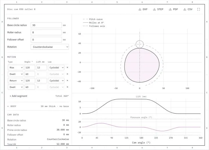
Change a setting and the cam is drawn again. The segments run from the cam angle 0°, where the follower stands on the base circle, and add up to 360°, and the returns bring the follower back as far as the rises lift it. DXF and STEP hold the cam's face in millimeters, the PDF an A4 sheet with the cam, its lift diagram and its data, and the CSV file the lift, velocity, acceleration and pressure angle for every degree.
What the cam profile generator draws
A disc cam that moves a translating roller follower through a given motion, as a flat outline to cut or extrude.
A disc cam turns at constant speed and pushes a follower along a straight line. The follower's motion over one turn is the cam's program, made of rises, where the follower moves out, dwells, where it stands still, and returns, where it moves back. The generator draws the cam from this program and the sizes of the follower. It also reports the pressure angle and the smallest radius of the pitch curve, the two values that decide whether the cam runs well.
The motion laws
Over a segment of angle β, the follower moves through the lift h along a motion law in u = θ/β, the fraction of the segment, with θ counted from the segment's start. The four laws differ in how the follower starts and stops.
- The cycloidal law, s = h [u − sin(2πu)/(2π)], starts and ends with zero velocity and zero acceleration, so the follower runs smoothly into and out of a dwell, even at speed.
- The simple harmonic law, s = h (1 − cos πu)/2, starts and ends with zero velocity, but its acceleration jumps where it meets a dwell.
- The 3-4-5 polynomial, s = h (10u³ − 15u⁴ + 6u⁵), also has zero velocity and acceleration at both ends, with a lower peak acceleration than the cycloidal law.
- Constant velocity, s = h u, has an infinite acceleration where the segment starts and ends. The follower knocks there, and the generator gives a note.
The pitch curve and the prime circle
The roller's center travels along the pitch curve. At the cam angle 0°, the follower stands on the base circle, the smallest circle of the cam, and the roller's center lies on the prime circle of radius Rp = Rb + r, the base circle radius plus the roller radius. With the follower's axis offset by e from the cam's center, the roller's center starts at d = √(Rp² − e²) along the axis and lies at d + s(θ) at the cam angle θ.
Pressure angle
The pressure angle φ is the angle between the follower's axis and the normal of the pitch curve, the direction in which the cam pushes the roller. For a translating follower, tan φ = (ds/dθ ∓ e)/(d + s), with the sign of e set by the direction of rotation. A large pressure angle presses the follower sideways into its guide, and the usual limit for a translating follower is 30°. A larger base circle or a longer rise angle lowers it, and an offset follower lowers it on the rise at the cost of the return. The generator reports the largest pressure angle and the cam angle where it occurs.
Undercut
The cam's outline lies inside the pitch curve, at the roller radius. Where the pitch curve bulges outward and bends tighter than the roller radius, the outline would cross itself, so the cam is undercut and the follower cannot follow the motion there. The generator computes the pitch curve's radius of curvature over the whole turn and reports its smallest value where the curve bulges outward, together with the outline's radius there, the pitch curve's radius minus the roller radius. Where the pitch curve is hollow, the outline lies further from the center of curvature and cannot be undercut. A roller radius of 0 is a knife-edge follower, whose outline is the pitch curve itself.
Bore and keyway
A bore diameter above 0 cuts a bore at the cam's center, and a keyway width and depth cut a keyway into its top. The depth t2 counts from the bore's edge, as keyway tables give it for the hub.
Units
Sizes and lifts are in millimeters and angles in degrees. The velocity and acceleration are taken per radian of cam rotation, in mm/rad and mm/rad². For a cam turning at ω in rad/s, multiplying them by ω and ω² gives the follower's velocity in mm/s and its acceleration in mm/s².
How the cam profile generator works
The generator is a small page around the planex2d Python library. It runs the same code you get with pip install planex2d, compiled to WebAssembly and loaded with Pyodide/ngapp.
- Load
The page loads Python and planex2d into this tab. Your browser keeps both in its cache, so later visits start faster.
- Draw
planex2d draws the cam for the settings, again whenever one changes.
- Save
The cam is saved as DXF, STEP, PDF or CSV, made in the tab as well.
The outline
Every segment of the motion becomes one curve of the roller's center, an exact parametric curve of the cam angle, which planex2d fits as a spline to about 10⁻¹² of its size. The curves join into one closed loop, the pitch curve. The cam's outline is that loop offset inward by the roller radius, fitted within a millionth of the cam's size, far below any machining tolerance. The pressure angle and the radius of curvature follow from the motion's formulas and their derivatives, at every quarter degree of the turn. The tests check them against numeric derivatives of the drawn pitch curve, and check that the roller, centered on the pitch curve, touches the outline.
Supported files
| Format | Extensions | Notes |
|---|---|---|
| DXF | .dxf | The cam's outline in millimeters as splines, the bore as a circle, or as an arc and lines with a keyway. See Files. |
| STEP | .step | The cam as a flat face in millimeters, to extrude to its thickness in a CAD program. See STEP and BREP. |
.pdf | An A4 sheet with the cam and its pitch curve, at 1:1 when it fits, else at 1:2, 1:5 or the next standard scale that does, with the lift diagram, the cam data and a 50 mm line to check the print. | |
| CSV | .csv | The lift, velocity, acceleration, pressure angle and the roller center's position for every degree of the turn. |
Run it in Python
The generator's cam takes a few lines with the library. The example draws the default cam, a cycloidal rise of 12 mm over 120°, a dwell of 60°, the return over 120° and another dwell, for a base circle of 30 mm and a roller of 8 mm. Each segment is one expression curve for the roller's center at the distance r(t) from the cam's center, with the cam angle t in degrees. The rise is the cycloidal law above with u = t/120, and since the expressions take angles in degrees, sin(2πu) is written sin(3*t). The offset by the roller radius gives the outline. See Parametric curves and Offsets in the docs, and the disc cam practice drawing for a cam with its drawing.
$ pip install planex2dimport planex as px
rise = "38 + 12*(t/120 - sin(3*t)/(2*pi))"
fall = "50 - 12*((t - 180)/120 - sin(3*(t - 180))/(2*pi))"
pitch = px.QuickSketch((0, 38))
for r, angles in [(rise, (0, 120)), ("50", (120, 180)), (fall, (180, 300)), ("38", (300, 360))]:
pitch.Curve((f"({r})*sin(t)", f"({r})*cos(t)"), angles)
cam = pitch.Wire().Offset(-8).Face()
(left, bottom), (right, top) = cam.bounding_box
print("top", round(top, 6), "bottom", round(bottom, 6))
px.WriteDXF(cam, "cam.dxf", unit=px.mm, scale=1)It prints a top of 30 and a bottom of −42. The outline lies on the base circle at 0°, 30 above the center, and at the base circle plus the lift at 180°, 42 below it. The file cam.dxf holds the same outline as the generator's DXF file of the default cam.
Privacy
Nothing is uploaded. The cam is drawn in this tab, and its files are made there as well. Python, planex2d and its packages come from public package servers (jsDelivr and PyPI). See the privacy notice.
Limits
- The generator draws disc cams for translating roller and knife-edge followers. Flat-faced and oscillating followers and cylindrical cams are not included.
- The motion holds up to 12 segments. It starts on the base circle at 0°, and the returns must bring the follower back to it.
- The values are kinematic. Speeds, spring forces, contact stresses and the follower lifting off the cam at speed are not computed.
- The largest pressure angle and the smallest radius are found by checking every quarter degree of the turn, so the exact extremes may differ slightly.
- The STEP file holds a flat face, not a solid. The thickness appears in the cam data and on the PDF.
- A cam that fails or a result that looks wrong? Open an issue on GitHub and describe the settings.
Questions and answers
Which motion law should I choose?
For most cams, the cycloidal law or the 3-4-5 polynomial. Both start and end with zero velocity and zero acceleration, so the follower runs smoothly into and out of a dwell, and the 3-4-5 polynomial has the lower peak acceleration of the two. The simple harmonic law has a lower peak still, but its acceleration jumps where it meets a dwell. Constant velocity has an infinite acceleration where a segment starts and ends, and the follower knocks there, which only very slow cams tolerate.
What pressure angle is acceptable?
The usual limit for a translating roller follower is 30°. Above it, the side force on the follower's guide grows quickly, with more friction and wear, and the follower can jam. The diagram marks ±30°, and the generator gives a note when the largest pressure angle exceeds it. A larger base circle, a longer rise angle or a smaller lift lowers it. The default cam reaches 14.70° at a cam angle of 56.75°.
What is undercut, and how do I avoid it?
A cam is undercut where its pitch curve bulges outward and bends tighter than the roller radius. The outline would loop back on itself there, so the cam loses that part of the motion and the follower does not follow it. The generator gives a note when the smallest radius of such a stretch is not larger than the roller radius. A larger base circle, a smaller roller or a longer rise angle avoids it.
Can I open the cam in my CAD program?
Yes. The DXF file holds the cam's outline in millimeters, as splines, and the STEP file holds the cam as a flat face in millimeters. A CAD program that reads DXF or STEP extrudes the face to the cam's thickness. The outline in both files is the one the generator draws, accurate to a millionth of the cam's size.
Which followers does it support?
Translating roller followers, centered on the cam or offset from its center, for either direction of rotation. A roller radius of 0 gives a knife-edge follower, whose outline is the pitch curve itself. Flat-faced and oscillating followers are not included.
Is my design sent anywhere?
No. planex2d draws the cam in this browser tab, running on Pyodide/ngapp, and the files are made there as well. Python and its packages come from jsDelivr and PyPI, and the cam's sizes and motion never leave the tab.
Other tools on planex2d.org
Every tool runs on the planex2d library, in your browser.
-
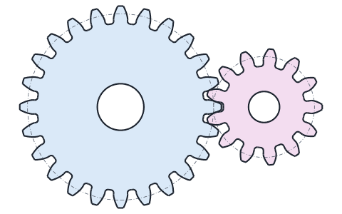
Gear generator
Involute spur gears, racks and ring gears from their module and number of teeth, with fillets, bores and keyways, saved as DXF, STEP, PDF and CSV.
-
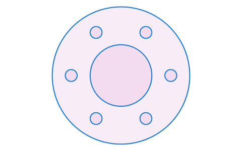
Converters
DXF, SVG, STEP and BREP files converted into one another or into PDF and PNG, many at once and at true size, with arcs and circles kept exact.
-
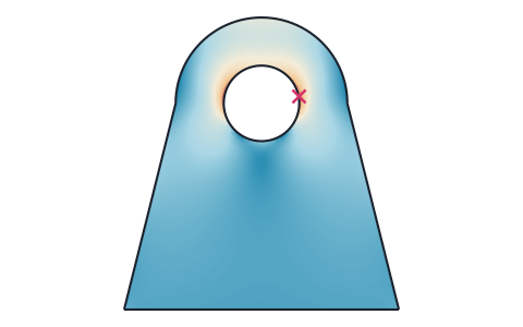
Stress analysis
Finite element stress analysis of flat parts from DXF, SVG or STEP files, with supports and loads by edge and hole number, the von Mises and principal stresses, the deformed shape and a safety factor.
-
Viewer
DXF, SVG, planar STEP and BREP files shown layer by layer, with the exact lines, arcs and splines that planex2d reads.
-
Playground
planex2d code in the browser, with OpenCASCADE for 3D solids and netgen and NGSolve for finite elements, shared as a link that carries the code.
The planex2d Online Tools page lists every tool, and the planex2d documentation shows the library behind them.