Tools / SVG to STL
SVG and DXF to STL and STEP
Turn an SVG or DXF drawing into a 3D model for 3D printing. Each color and each layer of the drawing can have its own height, so that a logo, a sign or a nameplate comes out in one step. A line can also become a wall of a set thickness, outside, inside or centered on it, as the blade of a cookie cutter. Save the model as STL for your slicer, or as STEP and BREP with exact arcs for CAD.
Nothing is uploaded. planex2d reads the drawing and builds the model in this browser tab with OpenCASCADE, running on Pyodide/ngapp, so your drawings stay on your computer and are never stored or shared. The tool is free to use, with no account and no license.
- Nothing is uploaded
- A height per color and layer
- Walls inside, outside or centered
- Built on the planex2d library
Reading
| On | Layer | Closed | Open | Type |
|---|
Open an SVG or DXF file or one of the samples below. The Layers table lists the drawing's colors and layers, with white switched off, since it is mostly the page behind the drawing. With Merge layers on, all of them form one part with the height set under Properties. With it off, click a layer to give it its own type and height. The model is built again after every change. Drag it to turn it and scroll to zoom. The STL file holds the surface as flat triangles, and the STEP and BREP files hold the exact solids, all in millimeters.
Try a sample drawing
Each one opens in the extrusion tool above with its layers set up.
-
Fig. 1SVG
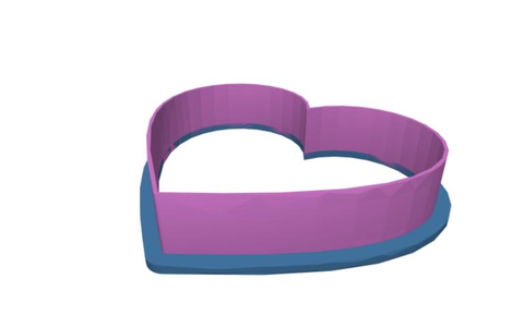
Cookie cutter
One heart outline on two layers, both made walls outside the outline: the blade 0.8 mm thick and 15 mm high, and the rim 4 mm wide and 2 mm high, which holds it together. They come out as one solid, ready to print as STL.
-
Fig. 2SVG
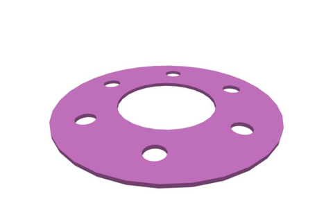
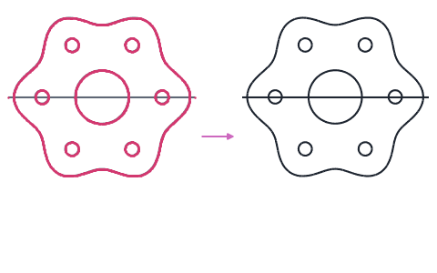
Flange gasket
A gasket 116 mm across with its bore and six bolt holes, as an SVG file in millimeters, padded to 2 mm as one part. Its STEP file keeps every circle exact for CAD.
-
Fig. 3DXF
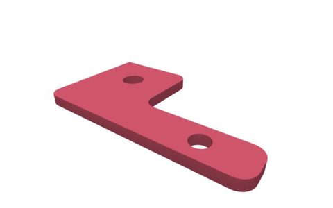
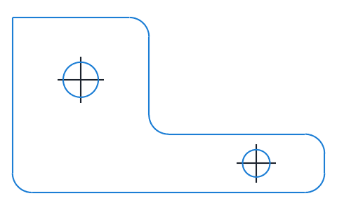
Mounting bracket
A bracket plate as a DXF file, padded to 8 mm. Its center lines lie on a layer of their own, which is switched off, so that only the contour is built.


What the extrusion tool builds
A 3D model from a flat drawing: every shape pushed straight up from the drawing's plane, as a pad or an extrusion in a CAD program.
A drawing made for a laser cutter, a plotter or a logo has the shape of a part but no thickness. The tool gives it one, for each color and each layer, and turns lines into walls where a part needs them. It reads an SVG file as it looks, so its filled areas and the widths of its strokes become faces. With Interpret as drawn ticked under the file, it reads only the file's lines instead, as CAD and laser cutting programs write them, leaves filled areas out and joins lines that meet end to end. A DXF file is read as drawn, and its hatches are left out. Lines that close on themselves become faces, and a shape inside another is a hole. Each face with its holes is pushed up into a solid of its height.
Colors, layers and their types
An SVG file has a layer for each color, within its Inkscape layers, and a DXF file has its own layers. White starts switched off, since it is mostly the page or a background. The table counts each layer's closed shapes and its open lines. With Merge layers on, all layers that are switched on form one part with one height. With it off, each layer has its own type and height:
- Solid pushes the layer's shapes up into solids. Lines that do not close become surfaces without thickness, and a note says on which layer.
- Offset puts a wall of the given thickness along every line, outside, inside or centered on a closed line and centered on an open one. Corners come out round, sharp or chamfered, and the ends of open lines round, flat or square.
- Cut cuts the layer's shapes out of the other layers' solids, through all of them or to a depth measured down from the model's top.
- Shell makes every line a surface without thickness, a closed line a tube.
- Off leaves the layer out.
Solids that overlap are united into one part. Below the plane extends a layer below the drawing's plane too, so that layers can start at different heights.
Units and size
The model is built in millimeters. A DXF file names its unit in its header, and one without a unit is read in millimeters. An SVG file gives its size in its width and height, and one that names no unit there counts in CSS pixels, 1/96 inch, as a browser draws it. The Reading group sets another unit or a scale for the whole drawing, and Join gaps joins line ends that lie closer than the given distance.
The files
The STEP and BREP files hold the model as OpenCASCADE builds it, with every arc a true cylinder and every flat face a plane, so a CAD program can edit and measure it. The STL file holds its surface as flat triangles, the ones the view shows, which 3D printing slicers read. A circle gets 26 to 32 of them whatever its size. STL has no unit, and the numbers are millimeters.
How the extrusion tool works
The tool is a small page around the planex2d Python library and its OpenCASCADE integration. It runs the same code you get with pip install "planex2d[occ]", compiled to WebAssembly and loaded with Pyodide/ngapp.
- Load
The page loads Python, planex2d, its OpenCASCADE build and netgen into this tab. Your browser keeps them in its cache, so later visits start faster.
- Read
planex2d reads the drawing with its colors and layers, an SVG file as it looks or, with Interpret as drawn, as lines. Lines stay exact lines, arcs and splines.
- Build
planex2d makes faces of the closed shapes with their holes, puts walls along lines with its offsets and pads everything into OpenCASCADE solids, again after every change.
- Save
OpenCASCADE writes the STEP and BREP files, and the triangles of the view go into the STL file, in the tab as well.
Supported files
| Format | Extensions | Notes |
|---|---|---|
| SVG | .svg | Paths, rectangles, circles, ellipses, lines and polygons with their transforms, read as they look (fills and strokes as faces) or as drawn (strokes as lines, fills left out); a layer for each color and Inkscape layer. See SVG. |
| DXF | .dxf | Lines, arcs, circles, polylines, splines and ellipses of the model space, blocks included, with their layers. Hatches, solids and wide polylines are left out. |
| STL | .stl | The surface as triangles, in millimeters, for 3D printing. |
| STEP | .step | The exact solids and surfaces in millimeters, for CAD programs. |
| BREP | .brep | OpenCASCADE's own format of the same model, without a unit. |
Run it in Python
The same model takes a few lines with planex2d. The example is the flange gasket sample: planex2d reads the circles on its layer cut as drawn, with the numbers in millimeters, nests them into a face with seven holes, and pads the face to 2 mm. See SVG and 3D solids in the docs.
$ pip install "planex2d[occ]"import planex as px
wires = px.FromSVG("flange-gasket.svg", layers=["cut"], scale=1, painted=False)
gasket = px.Face(wires)
px.Pad(gasket, 2).WriteStep("flange-gasket.step")It writes the gasket as a STEP file.
Privacy
Nothing is uploaded. The drawing is read and the model built and saved in this tab, and both are gone when you close it. Python and its packages come from public package servers (jsDelivr and PyPI), and planex2d's OpenCASCADE build from this site. See the privacy notice.
Limits
- Text set in a font is left out, in SVG files and in DXF files (TEXT and MTEXT), and a note says how many texts the file holds. Embedded pictures in an SVG file are left out as well. Convert text to paths or lines first.
- With Interpret as drawn, the stroke width of a line is not used, so a line drawn thick is read as its center line. The type Offset gives it a thickness.
- A DXF file's hatches, solids and wide polylines are left out, and its closed lines make the faces.
- Clip paths and masks are not applied.
- Lines that close without a fill nest by even and odd, so a shape inside a hole is solid again. A filled shape follows its own fill rule.
- Every layer is pushed straight up from one plane. Tapers, curved surfaces and other 3D shapes need a CAD program.
- Drawings with thousands of outlines, such as QR codes or traced pictures, take longer to build.
Questions and answers
Is my drawing uploaded?
No. planex2d reads the drawing and builds the model in this browser tab with OpenCASCADE, running on Pyodide/ngapp. The drawing is never sent anywhere, stored or shown to anyone, and you keep every right to it. It is gone when you close the tab. Python and its packages come from jsDelivr and PyPI, planex2d's OpenCASCADE build from this site.
How do I convert an SVG to STL?
Open the SVG file, set the height under Properties and save the STL file. A shape inside another becomes a hole. To give the colors of the drawing different heights, turn Merge layers off and click each color in the Layers table.
How do I convert a DXF file to STEP?
Open the DXF file, set the height and save the STEP file. Lines, arcs and circles stay exact in the STEP file, so a CAD program reads true cylinders and planes instead of a mesh. A DXF file without a unit is read in millimeters.
Why does the text in my SVG not show up?
Text set in a font is left out, and so are embedded pictures, and a note says how many texts the file holds. Convert the text to paths first, in Inkscape with Path > Object to Path or in Illustrator with Type > Create Outlines, and open the file again. In a DXF file, TEXT and MTEXT are left out the same way, and the CAD program converts them to lines or polylines.
What does Interpret as drawn do?
An SVG file shows its shapes as filled areas and as strokes of a width. Without the box ticked, the tool reads the file that way, as it looks, so a logo or a picture comes out as it appears, its strokes included. CAD and laser cutting programs write a part as stroked lines and mean only these. Tick Interpret as drawn to read only the lines. Each line is read along its path without its width, and filled areas are left out. Lines that meet end to end are joined, closed shapes become faces, and the type Offset puts walls along the lines. The samples are line drawings and open with the box ticked.
Why did my drawing come out as thin surfaces?
Lines that do not close become surfaces without thickness, and an outline with a small gap does not close either. Join gaps under Reading closes gaps up to its size, and the contour checker shows where they are. In an SVG file read with Interpret as drawn, a line drawn with a thick stroke is read as its center line, since the stroke width is not used, and the type Offset gives such a layer walls of the stroke's width. Without the box ticked, a stroke is read as the band it covers.
How do I make a cookie cutter from an SVG?
Put the outline on two layers, or in two colors, or open the cookie cutter sample. Turn Merge layers off and give both the type Offset, which puts a wall of a set thickness outside, inside or centered on the line. Make one a thin, tall wall as the blade and the other a wide, low wall as the rim. The tool unites them into one solid.
Why is the white part of my SVG left out?
White in an SVG file is mostly the page or a background behind the drawing. Each color of an SVG file is a layer of its own, and the white one starts switched off. Tick it in the Layers table to extrude it as well.
Can I open a DWG file?
No, the tool reads DXF and SVG. Save the drawing as DXF in your CAD program first.
Why are the curves in my STL file faceted?
The STL file holds the surface as flat triangles, the same ones the view shows. A circle gets 26 to 32 facets whatever its size, so the facets lie up to 0.28 mm inside a circle of 116 mm and about 1 mm inside one of 400 mm. The STEP and BREP files keep every arc and curve exact.
Other tools on planex2d.org
Every tool runs on the planex2d library, in your browser.
-
Converters
DXF, SVG, STEP and BREP files converted into one another or into PDF and PNG, many at once and at true size, with arcs and circles kept exact.
-
Viewer
DXF, SVG, planar STEP and BREP files shown layer by layer, with the exact lines, arcs and splines that planex2d reads.
-
Contour checker
Open contours, gaps, doubled lines and tiny edges found in DXF, SVG and STEP drawings and repaired, with arcs fitted to tessellated outlines.
-
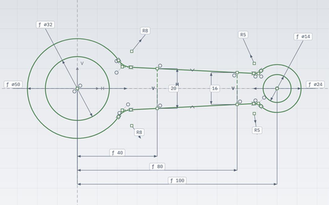
2D CAD Experimental
Constrained sketches with dimensions and formulas, a tree of operations, built-in simulations, dimensioned drawings, and DXF, SVG, STEP and BREP files.
-
Playground
planex2d code in the browser, with OpenCASCADE for 3D solids and netgen and NGSolve for finite elements, shared as a link that carries the code.
The planex2d Online Tools page lists every tool, and the planex2d documentation shows the library behind them.